Vehicle switching structure and new energy vehicle

A technology for vehicle use and switching components, which is applied in the field of vehicles, can solve the problems of different appearance and size of charging plugs, and the charging plug cannot be inserted into the socket, so as to achieve the effect of improving convenience and flexible use.

Active Publication Date: 2020-04-17
SHENZHEN BUSBAR SCI TECH DEV
View PDF7 Cites 3 Cited by
  • Summary
  • Abstract
  • Description
  • Claims
  • Application Information

AI Technical Summary

Problems solved by technology

[0004] One of the objectives of the present invention is to provide a switching structure for vehicles to solve the problem in the prior art that the charging plug needs to be inserted into the socket to be connected to the charging port. The appearance size of the plug is usually different. If the appearance size of the charging plug is too large, the technical problem that the charging plug cannot be inserted into the socket

Method used


Image

  • Vehicle switching structure and new energy vehicle
  • Vehicle switching structure and new energy vehicle
  • Vehicle switching structure and new energy vehicle

Examples


Embodiment 2

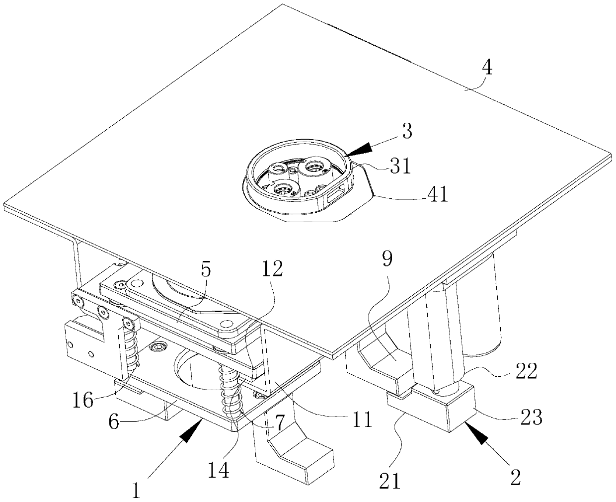
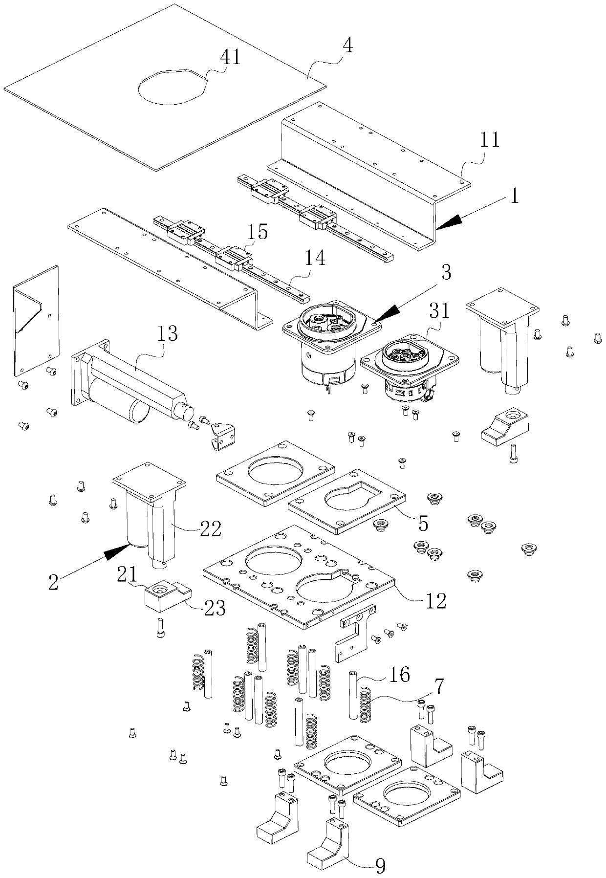
[0047] Example 2: Please refer to figure 1 and figure 2 , a switching structure for a vehicle, the difference from Embodiment 1 lies in the structure of the telescopic drive assembly 2 .

[0048] There are at least two telescopic control ends 21 of the telescopic drive assembly 2 . The telescopic drive assembly 2 realizes the setting of the number of telescopic control terminals 21 by setting the number of the second driving device 22 . The configuration of the second driving device 22 in this embodiment is different from that of the second driving device 22 in the first embodiment. Each second driving device 22 is in one-to-one correspondence with the charging port 31 . Each charging port 31 is fixed on the output end of the corresponding second driving device 22, and the second driving device 22 is connected to the sliding block 15 of the first embodiment.

[0049] Compared with the prior art, the user controls the switch assembly 1 according to the charging demand, so ...

Embodiment 3

[0050] Embodiment 3: a switching structure for a vehicle, the difference from Embodiment 2 lies in the structure of the telescopic drive assembly 2 .

[0051] Please also refer to figure 1 , figure 2 , Figure 7 and Figure 8 There are at least two telescopic control ends 21 of the telescopic drive assembly 2. The telescopic drive assembly 2 includes a guide 24, a transmission 25 and a rotary drive 26. The guide 24 is set as the telescopic control end 21 of the third embodiment. The guide member 24 has a guide surface 241, and the guide surface 241 is used for the corresponding charging port 31 to move along the guide surface 241 in a preset path. On the guide seat 11 of example one and be fixed on the transmission device 25, the rotary drive device 26 is arranged on the guide seat 11, the transmission device 25 is arranged on the guide seat 11, and the output shaft of the rotary drive device 26 is used to drive the transmission device 25 to The guide 24 is driven away fr...


PUM


Abstract

The invention provides a vehicle switching structure which is used for being arranged in a vehicle body. The vehicle switching structure comprises a switching assembly, a telescopic driving assembly and a plurality of charging ports. The switching assembly is provided with a switching movable terminal, the charging ports are connected to the switching movable terminal in a sliding mode, and the switching movable terminal drives the charging ports to be away from or close to an inserting port of the vehicle body; and all the charging ports are connected to the switching movable terminal in a sliding manner. The telescopic driving assembly has a telescopic control terminal that is used for enabling the charging port located at the inserting port to move from the interior of the vehicle bodyto the exterior of the vehicle body. The invention further provides a new energy vehicle which comprises the vehicle switching structure; and the purpose that after the direct current charging port and the alternating current charging port are switched, a charging plug is conveniently connected for charging is achieved.

Description

technical field [0001] The invention belongs to the technical field of vehicles, and more specifically relates to a switching structure for a vehicle and a new energy vehicle. Background technique [0002] As one of the means of transportation for people to travel, automobiles are widely used. Especially in recent years, with the advent of hybrid electric vehicles and electric vehicles, charging of automobiles has become a part of the daily life of car owners. [0003] For electric vehicles, two charging ports, DC and AC, are usually set up to meet the different needs of users for fast charging and slow charging. The existing charging port switching device for vehicles includes a switching unit and a driving unit. The switching unit is connected to the driving unit. The switching unit is provided with a plurality of charging ports. switch between charging ports. When the body is designed, it is necessary to reserve a plug-in interface for the charging port on the body. Th...

Claims


Application Information

Patent Timeline
Patent Type & Authority Applications(China)
IPC IPC(8): B60L53/16
CPCB60L53/16Y02T10/70Y02T10/7072Y02T90/14
Inventor 张毅徐平安林国军
Owner SHENZHEN BUSBAR SCI TECH DEV
Why Eureka
Try Eureka