New energy automobile charging device controlled by solar power supply

A new energy vehicle and solar power supply technology, which is applied in electric vehicle charging technology, electric vehicles, charging stations, etc., can solve the problems that solar panels cannot be adjusted, charging connectors are damaged, etc., and achieve the effect of low cost and convenient operation

Pending Publication Date: 2020-04-17
河南美力达汽车有限公司
View PDF7 Cites 0 Cited by
  • Summary
  • Abstract
  • Description
  • Claims
  • Application Information

AI Technical Summary

Problems solved by technology

However, the solar panel of this device cannot be adjusted according to the change of weather season. At the same time, when the new energy vehicle is charging, it cannot be simply protected from rain, which may easily cause damage to the charging connector.

Method used


Image

  • New energy automobile charging device controlled by solar power supply
  • New energy automobile charging device controlled by solar power supply
  • New energy automobile charging device controlled by solar power supply

Examples


Embodiment 1

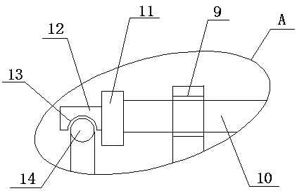
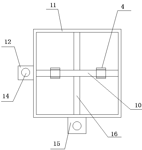
[0024] refer to Figure 1-5 , a new energy vehicle charging device controlled by solar power supply, comprising a base 17, a charging device body 18 is fixedly installed on the top side of the base 17, a rainwater shielding mechanism is arranged on one side of the charging device body 18, and the top of the charging device body 18 A top plate 1 is fixedly installed on the side, and a support rod 2 is fixedly installed on the top side of the top plate 1 along the vertical direction, and a mounting frame 3 is fixedly mounted on the top side of the support rod 2, and two vertical frames are fixedly mounted on the top side of the mounting frame 3 4. Turning holes 9 are provided on one side of the two vertical frames 4, and the same turning rod 10 is installed in the two turning holes 9, and a square sleeve 11 is rotated on the turning rod 10, and the square sleeve 11 A connecting column 5 is fixedly installed on the top side of the connecting column 5, and a solar panel 6 is fixed...

Embodiment 2

[0028] refer to Figure 1-5, a new energy vehicle charging device controlled by solar power supply, comprising a base 17, a charging device body 18 is fixedly welded on the top side of the base 17, a rainwater shielding mechanism is arranged on one side of the charging device body 18, the top of the charging device body 18 The side is fixedly welded with a top plate 1, the top side of the top plate 1 is fixedly welded with a support rod 2 along the vertical direction, the top side of the support rod 2 is fixedly welded with a mounting frame 3, and the top side of the mounting frame 3 is fixedly welded with two vertical frames 4. Turning holes 9 are provided on one side of the two vertical frames 4, and the same turning rod 10 is installed in the two turning holes 9, and a square sleeve 11 is rotated on the turning rod 10, and the square sleeve 11 A connecting column 5 is fixedly welded on the top side of the connecting column 5, and a solar panel 6 is fixedly welded on the top...


PUM


Abstract

The invention discloses a new energy automobile charging device controlled by solar power supply, including a base, wherein a charging device body is fixedly mounted on the top side of the base; a rainwater shielding mechanism is arranged on one side of the charging device body; a top plate is fixedly mounted on the top side of the charging device body; a supporting rod is fixedly mounted on the top side of the top plate in the vertical direction; a mounting frame is fixedly mounted on the top side of the supporting rod; two vertical frames are fixedly mounted on the top side of the mounting frame; rotating holes are formed in one sides of the two vertical frames; the same rotating rod is rotatably mounted in the two rotating holes; the rotating rod is rotatably sleeved with a square sleeve; a connecting column is fixedly mounted on the top side of the square sleeve; and a solar panel is fixedly mounted at the top end of the connecting column. The solar panel can be conveniently rotated and adjusted according to time and seasons, meanwhile, a flashing board can be conveniently and rapidly opened, the cost is low, and operation is convenient.

Description

technical field [0001] The invention relates to the technical field of new energy vehicle charging, in particular to a new energy vehicle charging device controlled by solar power supply. Background technique [0002] In recent years, people's demand for clean and reliable energy has increased, and "energy saving and emission reduction" in transportation has become a trend. Electric vehicles have gradually become a new hot spot for green energy saving. [0003] The patent application number 201710198848.3 discloses a new energy vehicle charging device controlled by solar power supply, including a body fixed on the top of the protective base and a rainproof shed above the body. There is a storage cavity inside the body, and the top of the storage cavity The body is provided with a first cavity and a second cavity, the top wall of the first cavity is provided with a sliding groove, the outer wall of the body on the right side of the storage cavity is provided with an operatio...

Claims


Application Information

Patent Timeline
Patent Type & Authority Applications(China)
IPC IPC(8): B60L53/30B60L53/51
CPCB60L53/30B60L53/51Y02T10/70Y02T10/7072Y02T90/12
Inventor 王冠豪轩飞王冲袁新刘凯
Owner 河南美力达汽车有限公司
Why Eureka
Try Eureka