Rock soil deep hole drilling equipment

A deep hole drilling and geotechnical technology, which is applied to drilling equipment, earthwork drilling, drilling tools, etc., can solve the problems of waste rock and soil being unable to output, rough hole walls, and low work efficiency, so as to achieve convenient and continuous output, internal hole smoothing effect

Active Publication Date: 2020-04-17
湖北省水文地质工程地质勘察院有限公司
View PDF10 Cites 2 Cited by
  • Summary
  • Abstract
  • Description
  • Claims
  • Application Information

AI Technical Summary

Problems solved by technology

[0002] When drilling deep holes in rock and soil, the waste rock and soil after the hole is often unable to be exported due to the deep depth, and the hole wall is relatively rough when the traditional hole turning device turns the hole, and there is a gap between the hole turning device and the soil discharge device. It can only work intermittently, resulting in low work efficiency, so it is necessary to set up a geotechnical deep hole drilling equipment to improve the above problems

Method used


Image

  • Rock soil deep hole drilling equipment
  • Rock soil deep hole drilling equipment
  • Rock soil deep hole drilling equipment

Examples


Embodiment Construction

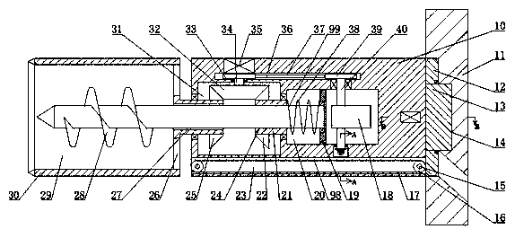
[0015] Combine below Figure 1-4 The present invention is described in detail, wherein, for the convenience of description, the orientations mentioned below are defined as follows: figure 1 The up, down, left, right, front and back directions of the projection relationship itself are the same.

[0016] A kind of geotechnical deep-hole drilling equipment described in conjunction with accompanying drawings 1-4, comprises a fuselage 10 and a block 11 located on the right side of the fuselage 10, and a rotating shaft is arranged in the left end wall of the fuselage 10 Cavity 31, the rotating tube 27 is arranged in the left end wall of the rotating cavity 31, the spline sleeve 21 is rotatably arranged in the right end wall of the rotating cavity 31, and the rightmost end of the rotating tube 27 is fixed An annular cutter 30 for rock and soil drilling is provided, and a crushing chamber 29 with an opening to the left is provided in the left end wall of the annular cutter 30, and a ...


PUM


Abstract

The invention relates to the field of rock soil drilling, in particular to rock soil deep hole drilling equipment. The rock soil deep hole drilling equipment comprises a machine body and a stop blocklocated on the right side of the machine body. A rotating cavity is formed in the end wall of the left side of the machine body. A rotating cylinder is rotationally arranged in the end wall of the left side of the rotating cavity. A spline sleeve is rotationally arranged in the end wall of the right side of the rotating cavity. An annular cutter used for rock soil drilling is fixedly arranged at the tail end of the rightmost side of the rotating cylinder. A crushing cavity with a leftward opening is formed in the end wall of the left side of the annular cutter. Through holes communicated withthe outside are formed in the right side end wall of the crushing cavity in a central symmetry manner. According to the rock soil deep hole drilling equipment, deep hole drilling of the rock soil canbe achieved, the equipment can crush the waste rock soil after drilling, then the rock soil is output through a conveying device arranged in the equipment, the equipment adopts the annular cutter to cut the rock body, cut inner holes are smoother, the equipment can conveniently continuously output the rock soil in deep holes, and higher efficiency is achieved.

Description

technical field [0001] The invention relates to the field of rock and soil drilling, in particular to a rock and soil deep hole drilling equipment. Background technique [0002] When drilling deep holes in rock and soil, the waste rock and soil after the hole is often unable to be exported due to the deep depth, and the hole wall is relatively rough when the traditional hole turning device turns the hole, and there is a gap between the hole turning device and the soil discharge device. It can only work intermittently, resulting in low work efficiency, so it is necessary to arrange a kind of rock and soil deep hole drilling equipment to improve the above problems. Contents of the invention [0003] The object of the present invention is to provide a rock and soil deep hole drilling equipment, which can overcome the above-mentioned defects of the prior art, thereby improving the practicability of the equipment. [0004] The technical solution adopted by the present inventio...

Claims


Application Information

Patent Timeline
Patent Type & Authority Applications(China)
IPC IPC(8): E21B4/16E21B12/00
CPCE21B4/006E21B4/16E21B12/00
Inventor 不公告发明人
Owner 湖北省水文地质工程地质勘察院有限公司
Why Eureka
Try Eureka