Pipeline fixing device for road construction

A technology for pipe fixing and road construction, which is applied in the directions of pipe supports, pipes/pipe joints/pipes, mechanical equipment, etc. It can solve the problems of poor applicability, easy displacement, and inability to adjust the pipe fixing device, and achieves easy adjustment and application scope. Wide and simple device structure

Active Publication Date: 2020-04-17
中国化学工程第四建设有限公司
View PDF14 Cites 5 Cited by
  • Summary
  • Abstract
  • Description
  • Claims
  • Application Information

AI Technical Summary

Problems solved by technology

[0002] In the existing road construction process, it is often necessary to lay pipelines. In order to prevent the pipeline from shifting, a clamp ring is usually installed on the pipeline. At the same time, most of the existing pipeline fixing devices cannot be adjusted, and the applicability is poor

Method used


Image

  • Pipeline fixing device for road construction
  • Pipeline fixing device for road construction
  • Pipeline fixing device for road construction

Examples


Embodiment 1

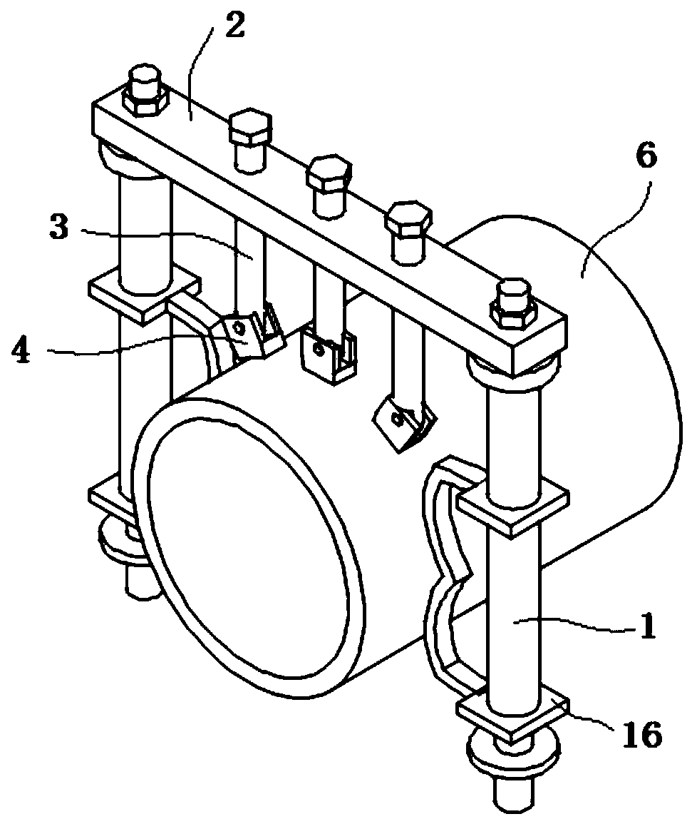
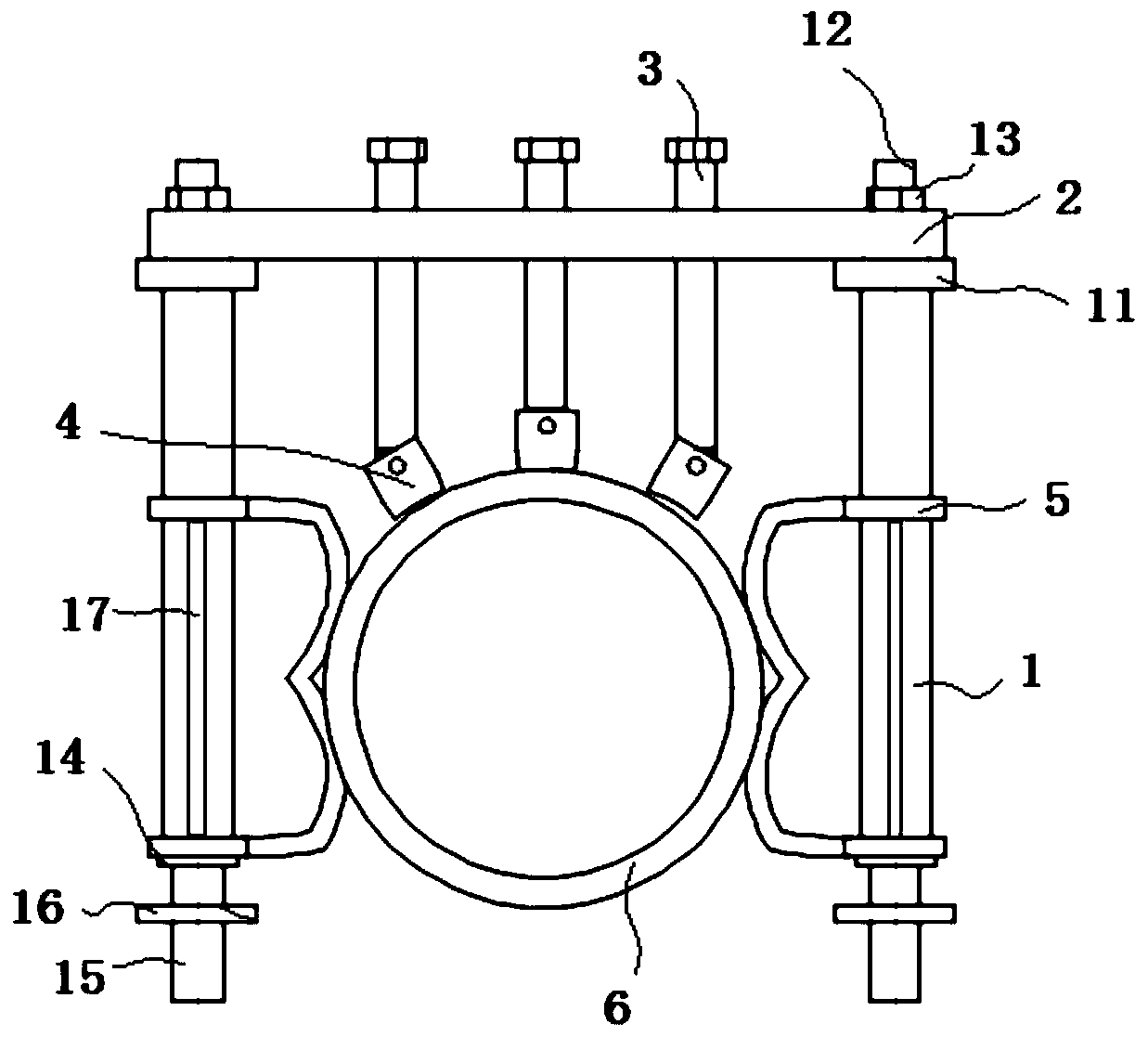
[0032] see Figure 1-5 As shown, a pipeline fixing device for road construction comprises two fixed piles 1 arranged in parallel, and a beam 2 is installed at the ends of the two fixed piles 1; The end is hinged with a block 4.

[0033] Preferably, the block 4 includes a base 41, the bottom side of the U-shaped base 41 is connected to an arc-shaped plate 44 through several buffer blocks 43, and the inner surface of the arc-shaped plate 44 is provided with a contact layer 45; the number of blocks 4 is 3 indivual.

[0034] Preferably, the base 41 is a U-shaped base, and the U-shaped base is provided with a hinge shaft 42 rotatably connected with the fixed screw rod 3 .

[0035] Preferably, the end of the fixed screw 3 is provided with a groove 21 and a shock absorbing spring 22 is fixed at the bottom of the groove 21, and the end of the shock absorbing spring 22 is fixed with a fixed substrate 23 that moves up and down along the groove 21; the fixed substrate 23 is connected ...

Embodiment 2

[0051] see Figure 1-3 Shown in and 6, a pipeline fixing device for road construction comprises two fixed piles 1 arranged in parallel, and a beam 2 is installed at the ends of the two fixed piles 1; The bottom end is hinged with clamping block 4.

[0052] Preferably, the block 4 includes a base 41, the bottom side of the U-shaped base 41 is connected to an arc-shaped plate 44 through several buffer blocks 43, and the inner surface of the arc-shaped plate 44 is provided with a contact layer 45; the number of blocks 4 is 3 indivual.

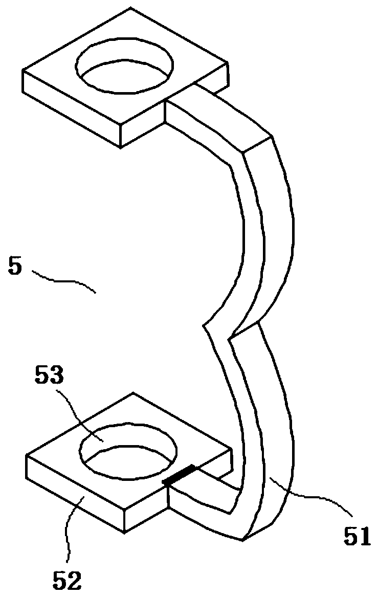
[0053] Preferably, both ends of the base 41 are provided with a hinge seat 46 and a hinge post 47 is provided on the hinge seat 46, and a connecting rod 6 is hinged on the hinge post 47;

[0054] Wherein, the two connecting rods 6 on the two adjacent blocks 4 are rotationally connected by a rotating shaft 61;

[0055] Wherein, between the base 41 and the fixed screw rod 3, there is a connecting rod with a cross-section of "I" shape; the connectin...


PUM


Abstract

The invention discloses a pipeline fixing device for road construction, and relates to the technical field of road construction. The pipeline fixing device includes two fixing piles arranged in parallel, and a cross beam is installed at the ends of the two fixing piles; at least two fixing screws are connected to the cross beam in a threaded mode, and clamping blocks are hinged to the bottom endsof the fixing screws; the clamping blocks include U-shaped bases, and the U-shaped bases are provided with hinge shafts which are rotatably connected with the fixing screws; the bottom side surfaces of the U-shaped bases are connected with arc-shaped plates through a plurality of buffer blocks, and contact layers are arranged on the inner side surfaces of the arc-shaped plates; and the two fixingpiles are provided with fixing pieces correspondingly, and the two fixing pieces are symmetrically arranged. According to the pipeline fixing device, fixing installation of pipelines in the road process is realized through combined use of the clamping blocks and the fixing pieces, and meanwhile, the device is suitable for fixing installation of a variety of pipelines with different sizes.

Description

technical field [0001] The invention belongs to the technical field of road construction, in particular to a pipe fixing device for road construction. Background technique [0002] In the existing road construction process, it is often necessary to lay pipelines. In order to prevent the displacement of pipelines, clamp rings are usually set on the pipelines. At the same time, most of the existing pipeline fixing devices cannot be adjusted, and the applicability is relatively poor. Contents of the invention [0003] The object of the present invention is to provide a pipe fixing device for road construction, so as to solve the problems raised in the above-mentioned background art. [0004] In order to solve the problems of the technologies described above, the present invention is achieved through the following technical solutions: [0005] The invention relates to a pipeline fixing device for road construction, which comprises two fixed piles arranged in parallel, and a ...

Claims


Application Information

Patent Timeline
Patent Type & Authority Applications(China)
IPC IPC(8): F16L3/02
CPCF16L3/02
Inventor 曹先女
Owner 中国化学工程第四建设有限公司
Why Eureka
Try Eureka