
Broaching tool handle assembly

A tool handle and component technology, applied in the field of broach tool handle components, can solve the problems of reducing the diameter of the tool handle neck, poor accuracy and stability, and easy breakage of the tool handle, so as to reduce the radial runout value, improve the accuracy, and improve the safety effect

Pending Publication Date: 2019-04-16
湖南南方机床有限公司
View PDF0 Cites 3 Cited by
  • Summary
  • Abstract
  • Description
  • Claims
  • Application Information

AI Technical Summary

Problems solved by technology

[0002] For the broaching machine, the ring groove handle has been included in the national standard, which is a very mature technology. However, with the development of automation technology, more and more small-diameter broaching, because the ring groove handle relies on The cone surface of the groove is centered by force, the cone surface is too small, the force is poor, the precision stability is poor, the cone surface increases, the diameter of the handle neck decreases, the strength also decreases, and the handle is easy to break

Method used


Image

  • Broaching tool handle assembly
  • Broaching tool handle assembly
  • Broaching tool handle assembly

Examples


Embodiment Construction

[0034] The present invention will be described in detail below in conjunction with the drawings and embodiments.

[0035] Reference Figure 1 to Figure 14 , A broach handle assembly of the present invention includes a broach 9 and a handle clamping device; the broach 9 includes a broach handle 91, the broach handle 91 has a tapered strip pull The knife handle 93, the strip broach shank 93 has a circular, elliptical or polygonal vertical axial section, and this embodiment is preferably a circular cross section; the knife handle clamping device is used to clamp the strip broach 93 to achieve opposite pulling The clamping of the knife 9 is fixed. Specifically, the tapered angle (the angle between the generatrix and the center line) of the strip broach 93 is β, and the value range of β is [-5°, 15°]; When the end extends and the radius becomes larger, β is a positive value, such as Picture 9 Shown is a positive angle, the taper that extends from the inside to the outside and incre...


PUM


Abstract

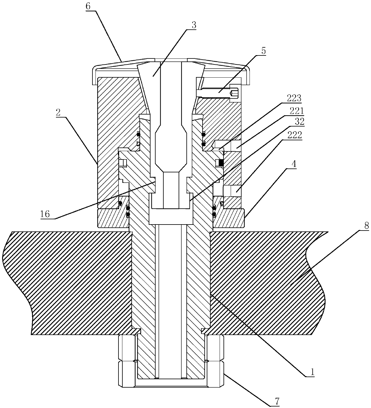
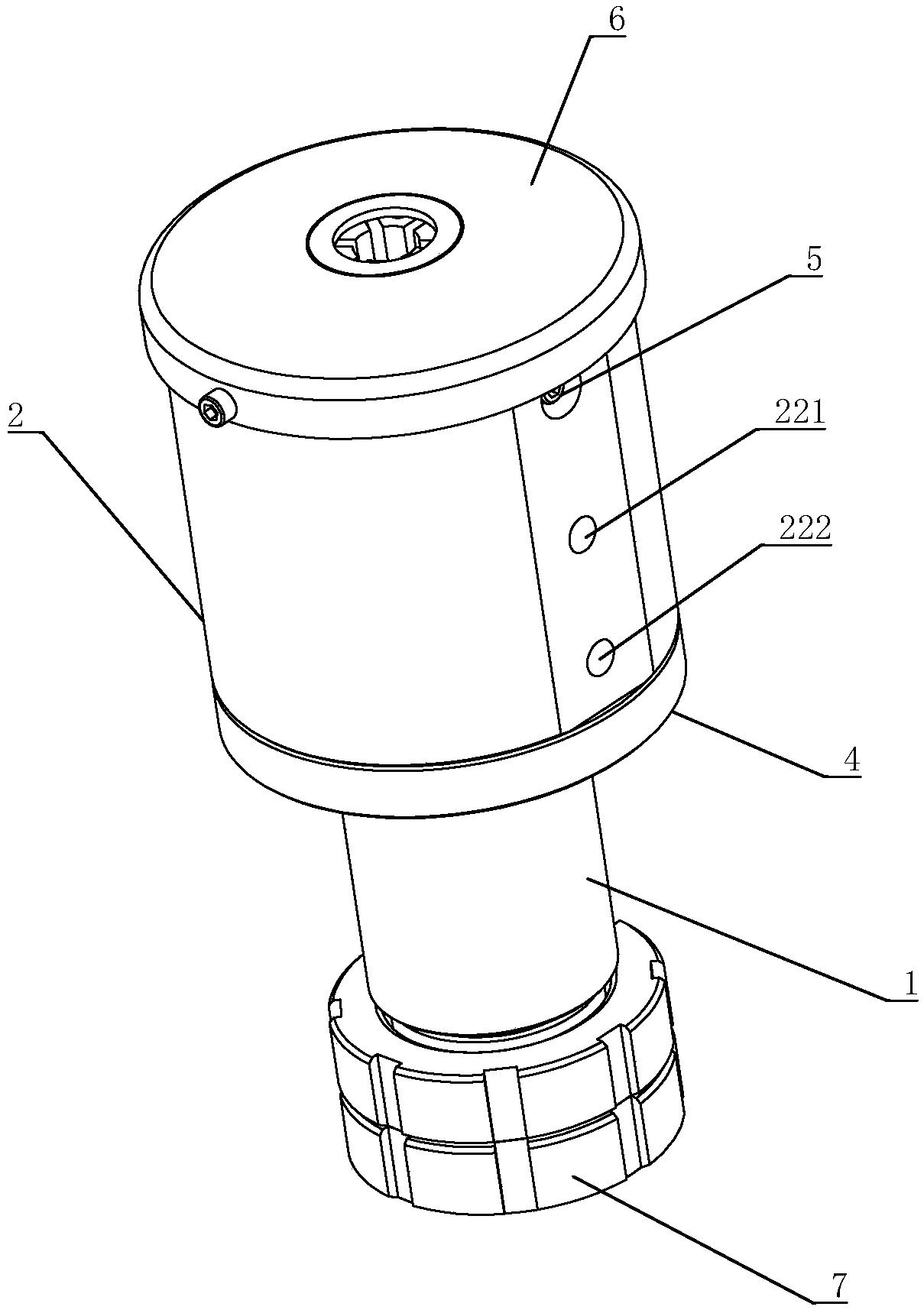
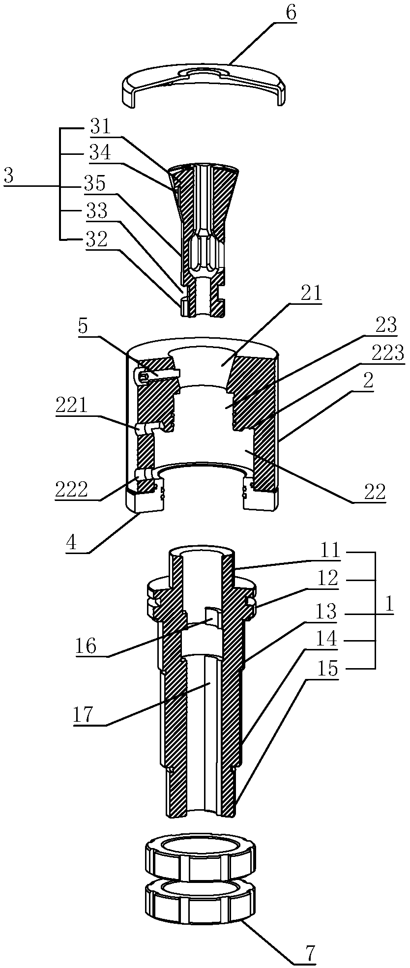
The invention discloses a broaching tool handle assembly. The broaching tool handle assembly comprises a broaching tool and a tool handle clamping device; the broaching tool comprises a broaching toolhandle, and the broaching tool handle is provided with a strip-shaped broaching tool handle body with the taper; and the tool handle clamping device is used for clamping the strip-shaped broaching tool handle body to achieve broaching tool clamping and fixing and bear broaching cutting force. According to the broaching tool handle assembly, for the broaching tool with the small diameter, a groovedoes not need to be formed in the broaching tool handle, the tool handle strength is improved, the precision and the stability are good, and the tool handle is not prone to being broken.

Description

Technical field [0001] The present invention relates to the field of broaching machine parts, in particular to a broach tool handle assembly. Background technique [0002] For broaching machines, the ring groove tool holder has been listed in the national standard, which is a very mature technology. However, with the development of automation technology, there are more and more small holes broaching, because the ring groove tool holder depends on The groove cone surface is centered by force, the cone surface is too small, the force is poor, the accuracy and stability are poor, the cone surface increases, the diameter of the tool holder neck is reduced, the strength is also reduced, and the tool holder is easy to break. Summary of the invention [0003] The present invention aims to solve the above technical problems at least to a certain extent. For this reason, the present invention provides a broach handle assembly that is easy to disassemble and replace. [0004] The technical ...

Claims


Application Information

Patent Timeline
Patent Type & Authority Applications(China)
IPC IPC(8): B23Q3/00B23B31/20B23D43/00
CPCB23B31/20B23D43/00B23Q3/00
Inventor 张又红
Owner 湖南南方机床有限公司
Learn More