Liquid crystal display panel and display device

A liquid crystal display panel and liquid crystal layer technology, applied in nonlinear optics, instruments, optics, etc., can solve the problems of being unable to prevent deformation of blind hole areas and easy slippage of contact points, and achieve the effect of preventing sag deformation

Inactive Publication Date: 2020-04-17
WUHAN CHINA STAR OPTOELECTRONICS TECH CO LTD
View PDF7 Cites 9 Cited by
  • Summary
  • Abstract
  • Description
  • Claims
  • Application Information

AI Technical Summary

Problems solved by technology

In the process of deformation in the blind hole area, the contact point of the support on the other substrate is prone to slipping, resulting in the inability to prevent the deformation of the blind hole area

Method used


Image

  • Liquid crystal display panel and display device
  • Liquid crystal display panel and display device
  • Liquid crystal display panel and display device

Examples


Embodiment Construction

[0031] The following descriptions of the various embodiments refer to the accompanying drawings to illustrate specific embodiments in which the invention may be practiced. The directional terms mentioned in the present invention, such as [top], [bottom], [front], [back], [left], [right], [inside], [outside], [side], etc., are only for reference The orientation of the attached schema. Therefore, the directional terms used are used to illustrate and understand the present invention, but not to limit the present invention. In the figures, structurally similar elements are denoted by the same reference numerals.

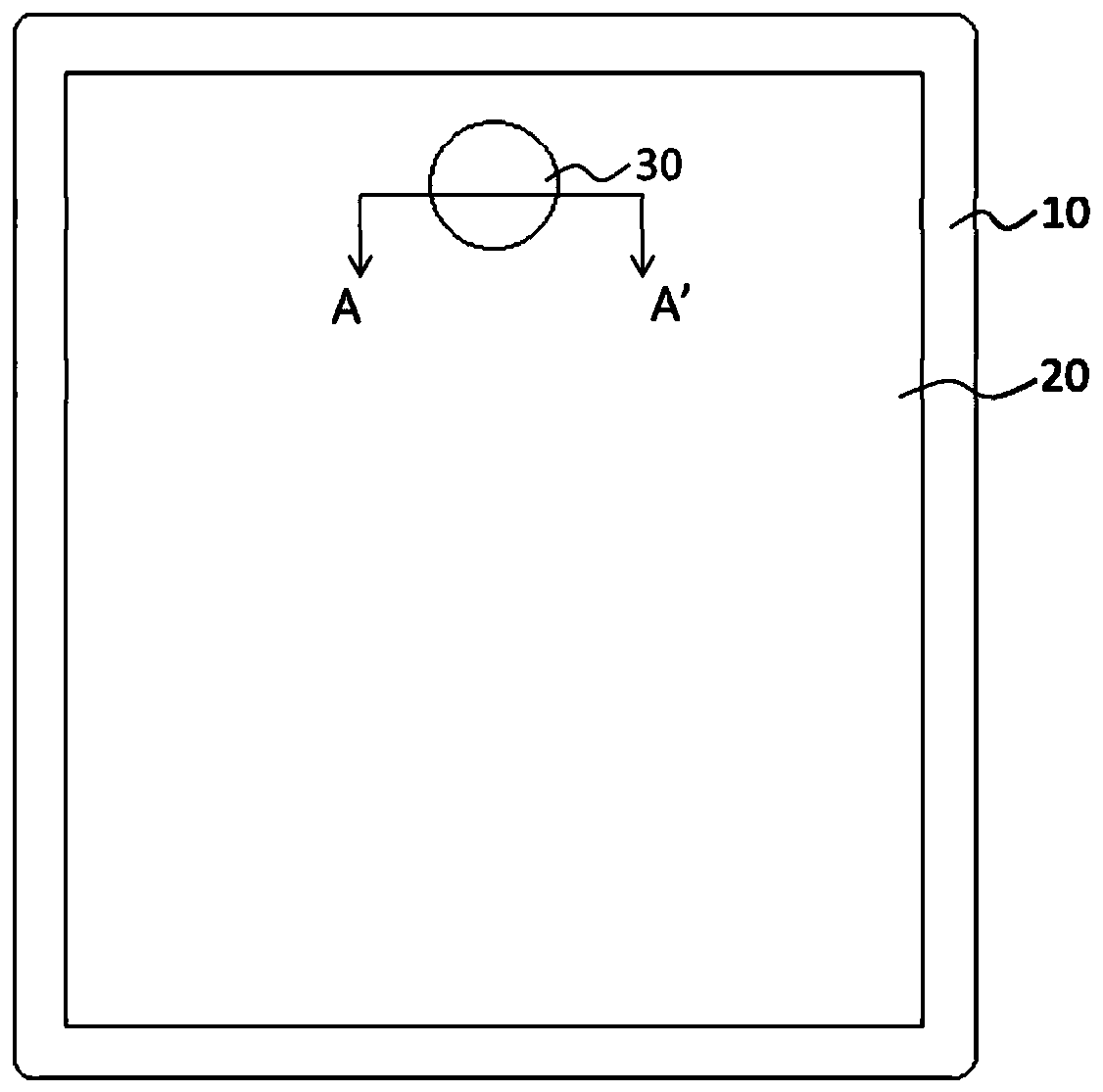
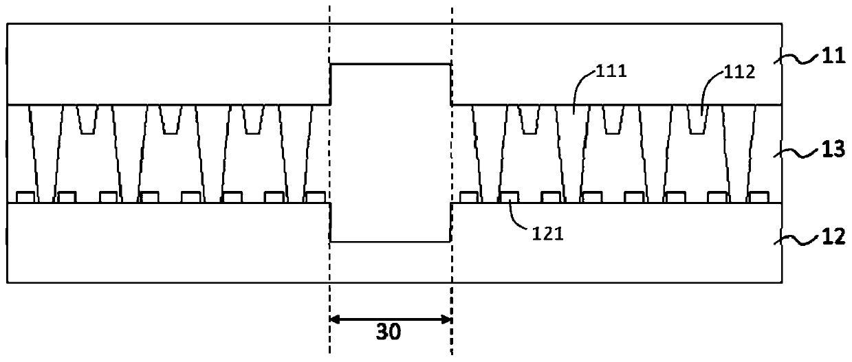
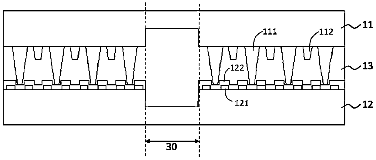
[0032] An embodiment of the present application provides a liquid crystal display panel. In order to prevent the support members around the blind hole area of ​​the liquid crystal display panel from slipping and causing the blind hole area to be deformed, the embodiment of the present application proposes that the second substrate around the blind hole area The metal t...


PUM


Abstract

The invention provides a liquid crystal display panel and a display device. The liquid crystal display panel comprises a first substrate, a second substrate and a liquid crystal layer, wherein a blindhole area is arranged in the liquid crystal display panel; a supporting piece is arranged on the side, facing the liquid crystal layer, of the first substrate; the first end of the supporting piece supports the first substrate; the second end of the supporting piece supports the second substrate; a plurality of metal wires protruding out of the surface are arranged on the side, facing the liquidcrystal layer, of the second substrate; the metal wires are arranged at intervals at least around the blind hole area; and the second end of the supporting piece is supported between every two adjacent metal wires. By means of the structural arrangement of the liquid crystal display panel, the situation that the blind hole area is sunken and deformed due to sliding of the supporting piece can be prevented.

Description

technical field [0001] The present application relates to the field of display technology, in particular to a liquid crystal display panel and a display device. Background technique [0002] Liquid crystal displays have the advantages of low power consumption, low flicker, and vivid picture colors, and are widely used in electronic products such as mobile phones, cameras, computer screens, and televisions, and are currently mainstream displays. [0003] With the development of display technology, the concept of full-screen design of display devices such as mobile phones has become more and more popular. In order to maximize the proportion of the display area in the display screen, panel developers have developed a hole-digging design and a blind hole design for the display area to meet the photosensitive requirements of the front optical device. The display screen with the hole-digging design cannot be displayed in the hole-digging area, thus limiting the further improvemen...

Claims


Application Information

Patent Timeline
Patent Type & Authority Applications(China)
IPC IPC(8): G02F1/1339G02F1/1362
CPCG02F1/13394G02F1/136286G02F1/13396G02F1/136222G02F1/133602G02F2201/121G02F2201/123
Inventor 吴咏波
Owner WUHAN CHINA STAR OPTOELECTRONICS TECH CO LTD
Why Eureka
Try Eureka