
Fire extinguishing protection power distribution cabinet

A technology for power distribution cabinets and cabinets, which is applied in substation/power distribution device shells, fire rescue, etc., and can solve problems affecting power safety, loss of power distribution cabinets, heat accumulation, etc., to reduce fire losses and accurately and quickly extinguish fires , Improve the effect of fire extinguishing rate

Active Publication Date: 2020-04-17
张燕 +2
View PDF10 Cites 8 Cited by
  • Summary
  • Abstract
  • Description
  • Claims
  • Application Information

AI Technical Summary

Problems solved by technology

[0003] As the types of power components in the power distribution cabinet become more and more integrated, a large amount of heat will be generated during operation. If the heat cannot be dissipated in time, it will easily lead to heat accumulation in the power distribution cabinet. , especially when some components in the power distribution cabinet are short-circuited, causing a fire
It not only causes damage to the distribution cabinet, but also directly affects the safety of electricity use.
In the prior art, only a flame sensor or a smoke sensor is installed in the distribution box, but no automatic fire extinguishing mechanism is installed, which easily delays the fire extinguishing time and causes irreparable losses in the distribution box.

Method used


Image

  • Fire extinguishing protection power distribution cabinet
  • Fire extinguishing protection power distribution cabinet
  • Fire extinguishing protection power distribution cabinet

Examples


Embodiment Construction

[0026] The following specific examples illustrate the implementation of the present invention. Those familiar with this technology can easily understand the other advantages and effects of the present invention from the contents disclosed in this specification. Obviously, the described embodiments are part of the embodiments of the present invention. , Not all examples. Based on the embodiments of the present invention, all other embodiments obtained by those of ordinary skill in the art without creative work shall fall within the protection scope of the present invention.

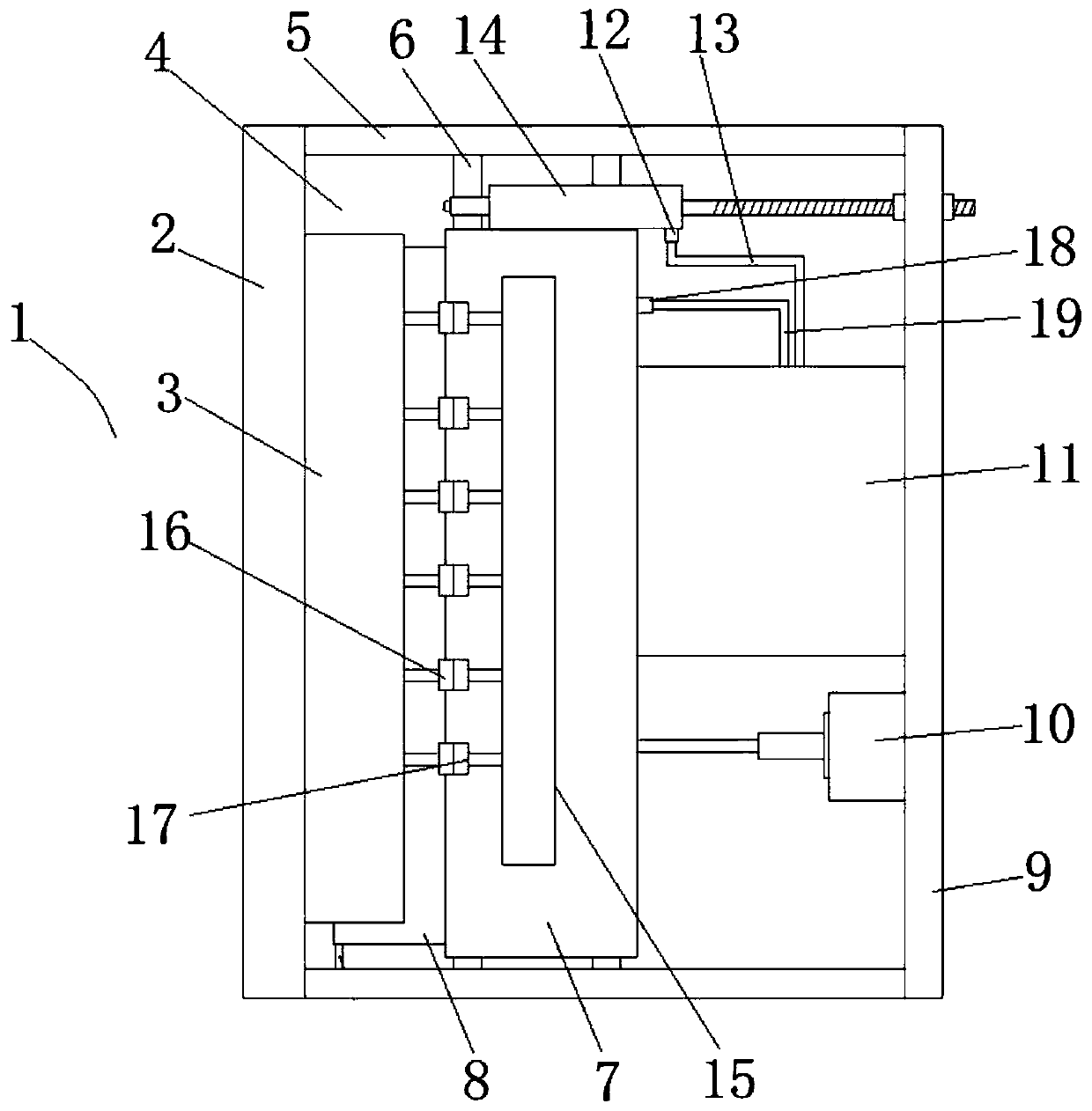
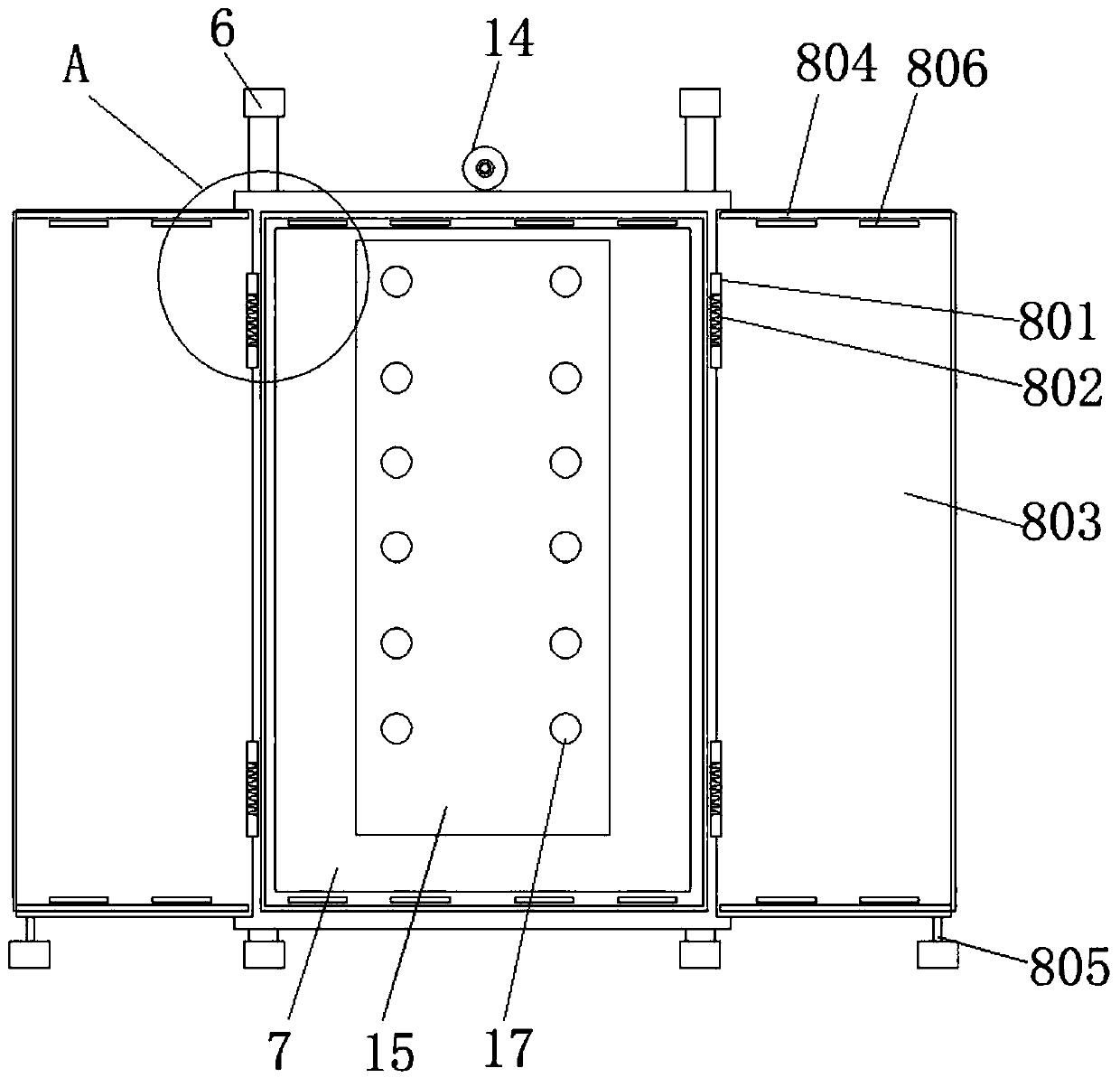
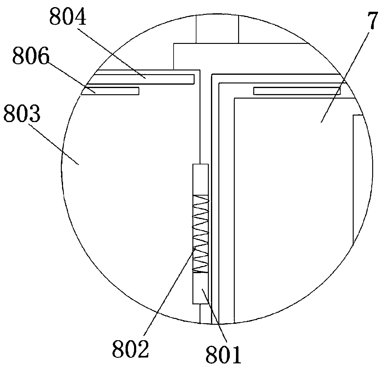
[0027] In order to solve the related technical problems in the prior art, an embodiment of the present application provides a fire-extinguishing protection power distribution cabinet, which includes a cabinet body 1. In order to achieve automatic detection of whether a fire occurs and automatic fire extinguishing functions, further Figure 1-5 , The installation board 2, the main board 3 of the power distrib...


PUM


Abstract

The embodiment of the invention discloses a fire extinguishing protection power distribution cabinet. The cabinet comprises a cabinet body, a power distribution cabinet main board is fixed on a mounting plate; the power distribution cabinet main board is provided with a first connecting plug. A supporting plate is arranged opposite to the mounting plate; a mounting cavity is formed between the supporting plate and the mounting plate; a sliding groove mechanism is arranged between the supporting plate and the mounting plate; a sliding seat is arranged in the sliding groove mechanism; a mountingbox is arranged on the sliding seat; a door opening-closing mechanism is arranged at a front end of the mounting box; a protective main board is arranged in the mounting box, a second connecting plugis arranged on the protective main board; the supporting plate is further provided with an air bag and a driving mechanism, inert gas is stored in the air bag, the air bag abuts against a rear end ofthe mounting box and is connected with a first control valve through a first air supply pipe, the first control valve is connected with a sand blasting device, the sand blasting device is fixed to anouter wall of the mounting box and faces the power distribution cabinet main board, and the driving mechanism is in transmission connection with the rear end of the mounting box. Inert gas can be sprayed outwards through the air bag, sand can be sprayed outwards through the sand spraying device, fire extinguishing is achieved, and the fire extinguishing speed and effect are improved.

Description

Technical field [0001] The embodiment of the present invention relates to the technical field of power equipment, in particular to a fire-extinguishing and protective power distribution cabinet. Background technique [0002] The power distribution cabinet is the terminal equipment of the power distribution system, which plays the role of connecting the previous and the next, especially the switch assembly that controls the power equipment is set in the power distribution cabinet. Therefore, it is very important to ensure the stable operation of the power distribution cabinet. [0003] As the types of power components in the power distribution cabinet become more and more integrated, a large amount of heat will be generated during operation. If the heat cannot be dissipated in time, it will easily lead to the accumulation of heat in the power distribution cabinet. , Especially when a short circuit occurs in some parts of the power distribution cabinet, causing a fire. Not only caus...

Claims


Application Information

Patent Timeline
Patent Type & Authority Applications(China)
IPC IPC(8): H02B1/28H02B1/30A62C3/16
CPCA62C3/16H02B1/28H02B1/30
Inventor 张燕王艳华蔺广芝
Owner 张燕
Learn More