Self-extinguishing device

An automatic fire extinguishing and fire extinguisher technology, applied in fire rescue and other directions, can solve the problem that fire extinguishing devices cannot extinguish fires in time, and achieve the effects of simple structure, reduced loss, and improved sensitivity

Inactive Publication Date: 2016-06-15
SUZHOU ZHENGXINTAI AUTOMATION SYST
View PDF0 Cites 5 Cited by
  • Summary
  • Abstract
  • Description
  • Claims
  • Application Information

AI Technical Summary

Problems solved by technology

[0003] The technical problem to be solved by the present invention is to provide an automatic fire extinguishing device to solve the problem that the fire extinguishing device equipped in the existing unattended power distribution room cannot extinguish the fire in time

Method used


Image

  • Self-extinguishing device
  • Self-extinguishing device
  • Self-extinguishing device

Examples


Embodiment Construction

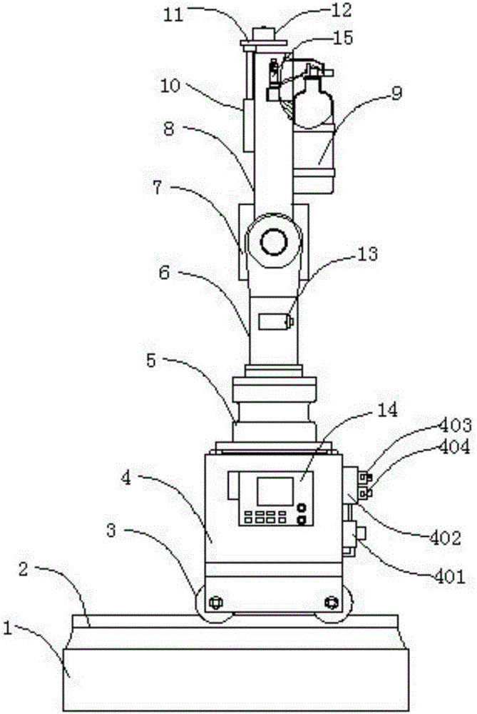
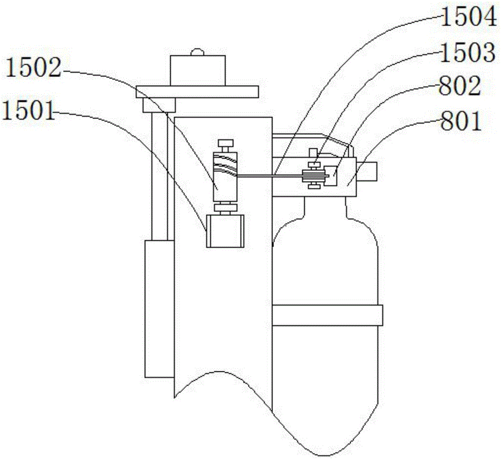
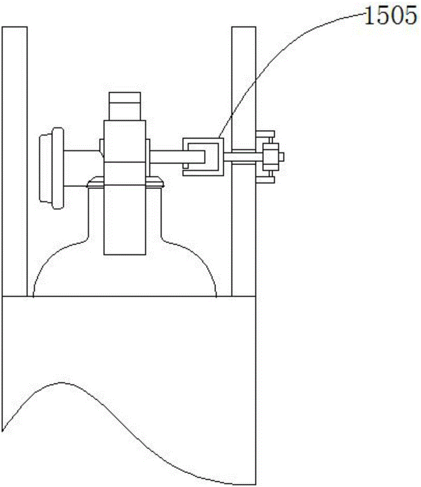
[0030] like figure 1 , figure 2 , image 3 As shown, an automatic fire extinguishing device includes a foundation 1, a track 2, a walking assembly 3, a fuel tank 4, a first rotary cylinder 5, a boom 6, a second rotary cylinder 7, a small arm 8, a fire extinguisher 9, and an electric push rod 10 , push plate 11, first visual sensor 12, second visual sensor 13, controller 14, safety release assembly 15, the track 2 is located at the upper end of the foundation 1, the track 2 is screwed to the foundation 1, and the The traveling assembly 3 is located at the upper end of the track 2, the traveling assembly 3 is rollingly connected with the rail 2, the fuel tank 4 is located at the upper end of the traveling assembly 3, the fuel tank 4 is threadedly connected with the traveling assembly 3, and the first rotating oil cylinder 5 is located at the upper end of the oil tank 4, the first rotary oil cylinder 5 is threadedly connected with the oil tank 4, the boom 6 is located at the u...


PUM


Abstract

The invention discloses an automatic fire extinguishing device, which comprises a foundation, a rail, a walking assembly, a fuel tank, a first rotary oil cylinder, a large arm, a second rotary oil cylinder, a small arm, a fire extinguisher, an electric push rod, a push plate, a first visual sensor, When the second visual sensor, controller, and safety release assembly work, when the first visual sensor or the second visual sensor detects an open flame or smoke, the controller controls the walking assembly to move on the track to the fire occurrence point, and passes the first The rotating oil cylinder and the second rotating oil cylinder adjust the posture of the boom and the forearm to adjust the fire extinguishing angle of the fire extinguisher. The controller controls the safety release component to work, opens the safety on the fire extinguisher, and the electric push rod drives the push plate to move downward, so that the fire extinguisher can extinguish the fire. The device has a simple structure and monitors the fire point in all directions without dead ends. At the same time, it can accurately extinguish the fire at a fixed point, greatly improving the fire detection sensitivity and reducing the loss caused by accidental fire.

Description

technical field [0001] The invention relates to a fire extinguishing device, in particular to an automatic fire extinguishing device. Background technique [0002] With the development of industry and the advancement of science and technology, more and more power distribution rooms and machine rooms adopt the unmanned on-duty mode. If a fire accident occurs, it will be fatal damage to the unmanned on-duty power distribution room. The room is equipped with a passive fire extinguishing device, which sprays water to extinguish the fire after the temperature rises or the smoke reaches a certain concentration, which has a certain hysteresis and inapplicability. In view of above-mentioned defective, be necessary to design a kind of automatic fire extinguishing device really. Contents of the invention [0003] The technical problem to be solved by the present invention is to provide an automatic fire extinguishing device to solve the problem that the fire extinguishing device eq...

Claims


Application Information

Patent Timeline
Patent Type & Authority Applications(China)
IPC IPC(8): A62C3/16A62C37/42
CPCA62C3/16A62C37/42
Inventor 时国平
Owner SUZHOU ZHENGXINTAI AUTOMATION SYST
Why Eureka
Try Eureka