Laser cloth cutting machine

A cloth cutting machine and laser technology, applied in laser welding equipment, welding equipment, metal processing equipment and other directions, can solve the problems of affecting cloth transmission, affecting the accuracy of cutting cloth, and large suction area, so as to improve transmission efficiency and precision, The effect of avoiding precision reduction and ensuring cutting precision

Pending Publication Date: 2020-04-21
江苏法斯特激光智能科技有限公司
View PDF0 Cites 0 Cited by
  • Summary
  • Abstract
  • Description
  • Claims
  • Application Information

AI Technical Summary

Problems solved by technology

[0002] In the setting structure of the existing laser cloth cutting machine, it is usually necessary to set up a cutting bed frame for supporting the overall structure, a cloth transmission structure installed on the frame, and a suction fixing device for fixing the cloth and driving it together with the transmission structure. Device and laser cutting assembly for matching cloth cutting; the transmission mechanism of the cloth cutting machine in the prior art is usually driven by a driving device, the upper and lower layers of the transmission mesh belt are directly arranged in parallel, and each suction assembly is installed accordingly At the lower position of the transmission belt, it can only be close to the position of the lower mesh belt of the transmission mesh belt, and there is a large distance between it and the upper mesh belt, resulting in insufficient suction and affecting the transmission of the cloth; in addition, the transmission mesh belt of the existing device After the leveling is set, the tension adjustment is not very convenient; and the suction components of the existing device are directly installed inside the fra

Method used


Image

  • Laser cloth cutting machine
  • Laser cloth cutting machine
  • Laser cloth cutting machine

Examples


Embodiment Construction

[0018] The present invention will be further illustrated below in conjunction with the accompanying drawings and specific embodiments. This embodiment is implemented on the premise of the technical solution of the present invention. It should be understood that these embodiments are only used to illustrate the present invention and are not intended to limit the scope of the present invention.

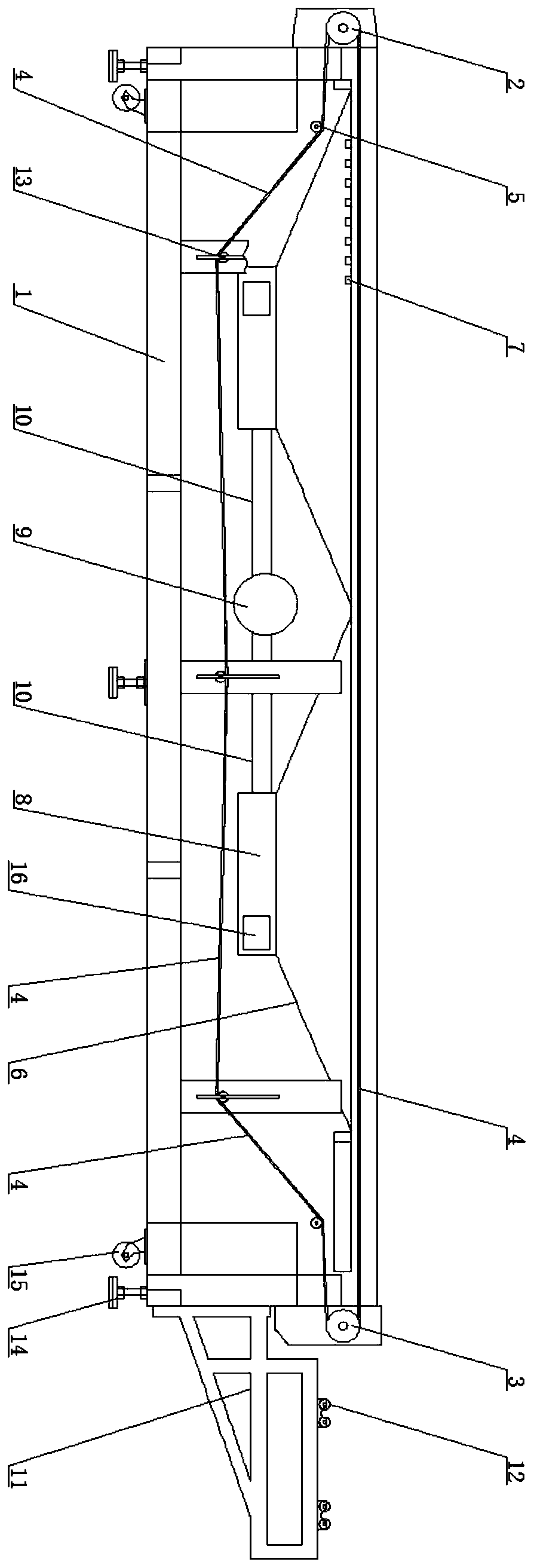
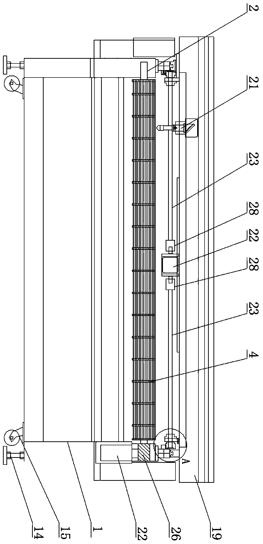
[0019] Such as figure 1 As shown, a laser cloth cutting machine includes a frame 1; a driving shaft 2 is provided on the front side of the upper end of the frame 1, and a corresponding driven shaft 3 is provided on the rear side of the upper end, and the driving shaft 2 and the driven shaft 3 are arranged between There is a transmission mesh belt 4, the upper layer mesh belt of the transmission mesh belt 4 is a plane structure used to drive the cloth, and the lower layer mesh belt of the transmission mesh belt 4 is guided by the guide shaft 5 provided on the frame 1 and then from the fra...


PUM


Abstract

The invention discloses a laser cloth cutting machine. The laser cloth cutting machine comprises a rack, wherein a transmission mesh belt is arranged on the rack; a lower-layer mesh belt of the transmission mesh belt is of a concave structure and is used for mounting an air suction assembly; an air suction cover body is arranged below the lower-layer mesh belt and an air suction pipe connected with the air suction cover body is mounted to generate suction force; sliding rails are further mounted on two sides of the upper end of the rack through vertical beams and a movable bracket is mounted through a sliding block; a driving motor is mounted at the middle part of the lower end face of the movable bracket; synchronous driving rods are mounted through a coupler; and a driving gear is mounted at the rod end and is engaged with a toothed bar on the rack to mount and drive the movable bracket. According to the laser cloth cutting machine, the air suction assembly can be mounted through a space between the upper and lower mesh belts, so that the air suction assembly can be close to the upper-layer mesh belt, the air suction amount is increased and cloth is effectively fixed; and furthermore, the driving motor can be used for bidirectionally driving the synchronous driving rods on two sides and driving two sides of the movable bracket to move, so that the transmission precision of the cloth is effectively improved.

Description

technical field [0001] The invention relates to the technical field of laser cloth cutting machines, in particular to a laser cloth cutting machine. Background technique [0002] In the setting structure of the existing laser cloth cutting machine, it is usually necessary to set up a cutting bed frame for supporting the overall structure, a cloth transmission structure installed on the frame, and a suction fixing device for fixing the cloth and driving it together with the transmission structure. Device and laser cutting assembly for matching cloth cutting; the transmission mechanism of the cloth cutting machine in the prior art is usually driven by a driving device, the upper and lower layers of the transmission mesh belt are directly arranged in parallel, and each suction assembly is installed accordingly At the lower position of the transmission belt, it can only be close to the position of the lower mesh belt of the transmission mesh belt, and there is a large distance b...

Claims


Application Information

Patent Timeline
IPC IPC(8): B23K26/38B23K26/402B23K26/70
CPCB23K26/38B23K26/402B23K26/702
Inventor 许秋阳王永凤
Owner 江苏法斯特激光智能科技有限公司
Why Eureka
Try Eureka