
A gear ring heat sealing device

A technology of gear rings and mounting brackets, applied in metal processing equipment, metal processing, manufacturing tools, etc., can solve the problems of inability to judge the pressure value, high cost, and low production efficiency

Active Publication Date: 2021-08-20
WUHU DONGGUANG DAHUA MACHINERY MFG
View PDF0 Cites 0 Cited by
  • Summary
  • Abstract
  • Description
  • Claims
  • Application Information

AI Technical Summary

Problems solved by technology

However, the existing press-fitting equipment for the ring gear and the heating equipment for the gear teeth are two separate devices, and the production efficiency is low, and the lower electrode plate of the existing gear tooth heating equipment is fixedly installed on the workbench On the above, it is necessary to manually place the material under the pressing device or heating device, the safety factor is low, and the pressing device cannot judge the pressure value during the pressing process, which may cause poor pressing effect. For material conveying, on the one hand, since the stroke of the cylinder is fixed, its placement point is fixed and cannot be adjusted. In order to facilitate the placement of the flywheel, the pull-out distance needs to be longer than the flywheel with a large diameter, and the diameter is small. The flywheel can be pulled out with a shorter distance. On the other hand, the equipment cost is high, which is not suitable for some small production enterprises.
[0004] In addition, during the production process of the flywheel, pins need to be pressed on the edge of the flywheel. The traditional installation method is to install the pins manually. The installation efficiency is low, and it is easy to have the problem of less or missing pins. The installation of the existing column pins and the pressing of the flywheel and the ring gear are carried out separately, resulting in low production efficiency

Method used


Image

  • A gear ring heat sealing device
  • A gear ring heat sealing device
  • A gear ring heat sealing device

Examples


Embodiment Construction

[0027] In order to make the technical means, creative features, goals and effects achieved by the present invention easy to understand, the present invention will be further described below in conjunction with specific embodiments.

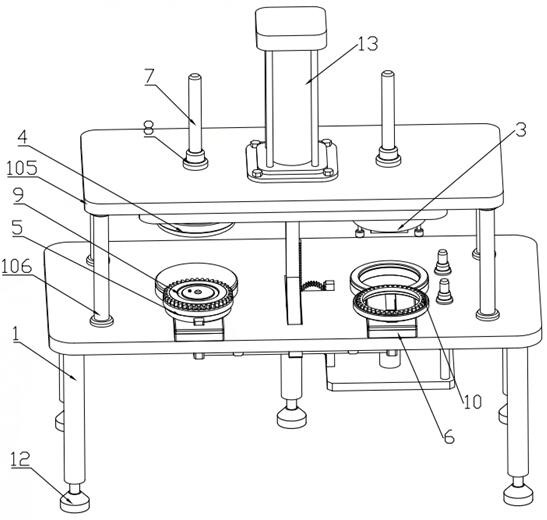
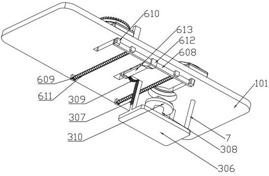
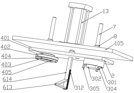
[0028] Such as Figure 1 to Figure 10As shown, a gear ring heat sealing device includes a mounting frame 1, a mounting plate 105 is connected to a supporting plate 101 of the mounting frame 1 through a supporting rod 106, a hydraulic cylinder 13 is vertically installed on the mounting plate 105, and The piston rod of the hydraulic cylinder 13 runs through the mounting plate 105 and the lower pressing plate 2 is installed through the handle. The lower end of the lower pressing plate 2 is provided with a pressing assembly 4 and a heating assembly 3. The supporting plate 101 is provided with a U-shaped stop plate 102 and moving assembly 6, and the moving rod 614 in the moving assembly 6 is fixedly installed on the lower end surface of the lower press...


PUM


Abstract

The invention discloses a heat-sealing device for a gear ring, which relates to the technical field of flywheel manufacturing, and includes a mounting frame on which a pressing assembly, a heating assembly, a moving assembly and a flywheel placement assembly are arranged. The pressing of the flywheel, and through a hydraulic cylinder, can realize the heating of the ring gear, the pressing of the flywheel and the ring gear, and the installation of the pin at the same time, which reduces the driving components, reduces the cost, and solves the existing labor problem. Place the flywheel and ring gear to increase safety, and at the same time avoid the problems of under-installation and missing-installation caused by manual installation of pins, and increase production efficiency.

Description

technical field [0001] The invention relates to the technical field of flywheel manufacturing, in particular to a gear ring heat sealing device. Background technique [0002] A flywheel is a rotating member with a proper moment of inertia, which stores and releases kinetic energy. It is commonly found in machines, automobiles, bicycles, etc., and is a wheel-shaped accumulator with a large moment of inertia. The flywheel is a wheel-shaped accumulator with a large moment of inertia installed on the rotary shaft of the machine. When the speed of the machine increases, the kinetic energy of the flywheel increases and the energy is stored; when the speed of the machine decreases, the kinetic energy of the flywheel decreases and the energy is released. Flywheels can be used to reduce speed fluctuations during mechanical operation. [0003] During the processing of the flywheel, the gear teeth and the flywheel are first manufactured separately, and then put together. The existin...

Claims


Application Information

Patent Timeline
Patent Type & Authority Patents(China)
IPC IPC(8): B23P11/02
CPCB23P11/025
Inventor 李姚谷生金宋立新孙洪明
Owner WUHU DONGGUANG DAHUA MACHINERY MFG
Learn More