Separable locking transmission device

A transmission device and locking technology, applied in the field of mechanical transmission, can solve the problem that the rotating shaft cannot be locked, and achieve the effect of convenient separation and combination

Pending Publication Date: 2020-04-21
BEIJING XIANJIN ROBOT CO LTD
View PDF0 Cites 0 Cited by
  • Summary
  • Abstract
  • Description
  • Claims
  • Application Information

AI Technical Summary

Problems solved by technology

[0002] When the drive motor output shaft and the rotating shaft are connected to the transmission, sometimes the rotating shaft and the output shaft of the driving motor can be easily separated and combined, such as the connection between the output shaft of the driving motor at the bottom of the juicer and the shaft of the mixer, such as the shaft of the razor blade The connection with the output shaft of the drive motor; but when the shaft is separated from the output shaft of the drive motor, the shaft cannot be locked and can rotate freely, which is not allowed in some occasions, so it is necessary to design a drive motor output shaft and The rotating shaft is easy to separate and combine, and the rotating shaft can be locked after the rotating shaft is separated from the drive motor

Method used


Image

  • Separable locking transmission device
  • Separable locking transmission device
  • Separable locking transmission device

Examples


Embodiment 1

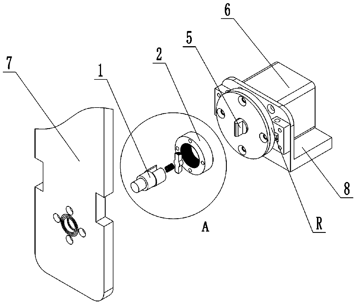
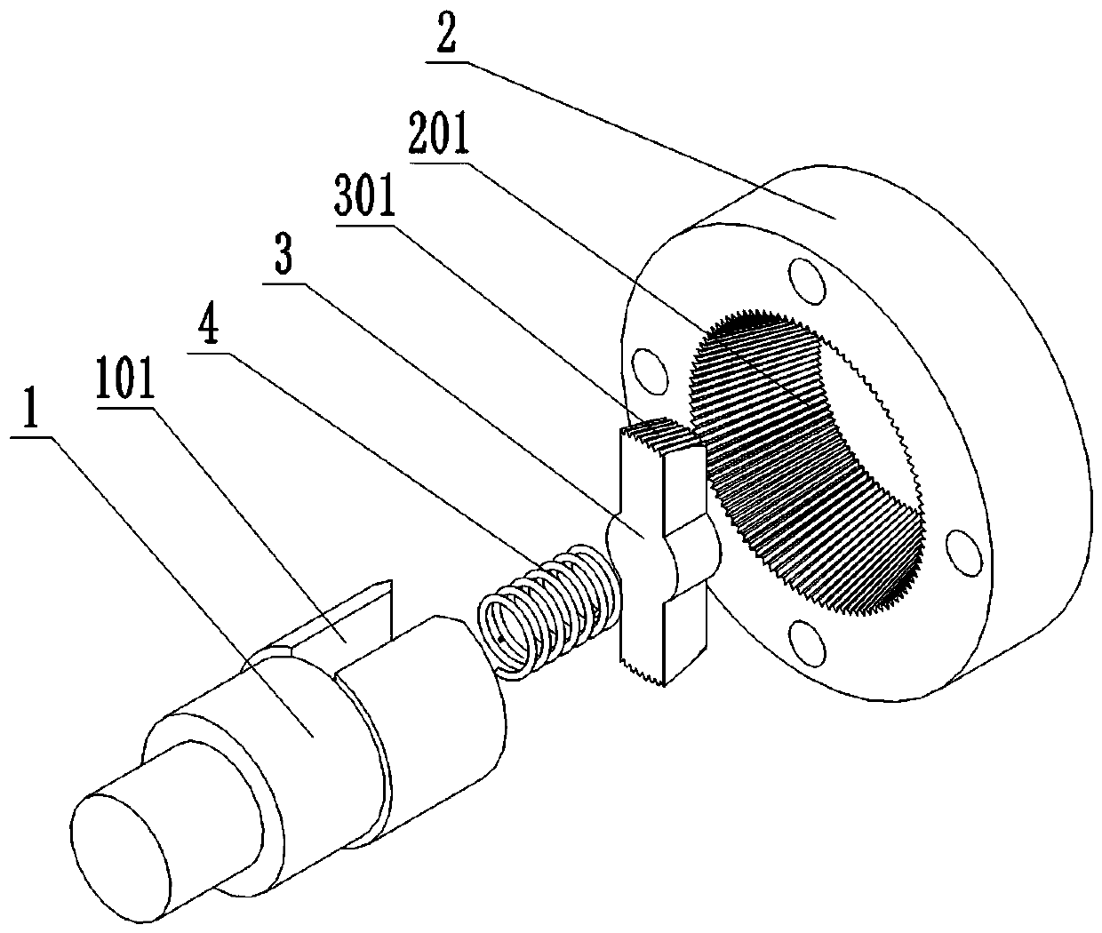
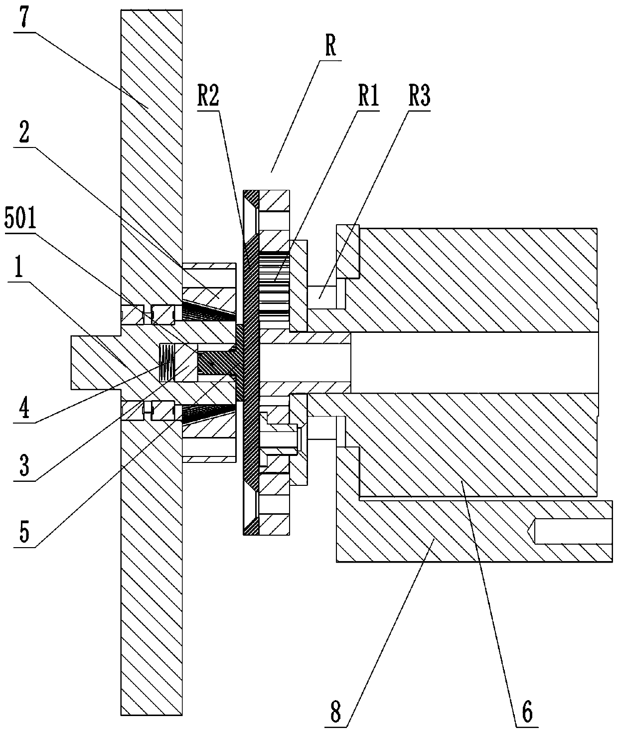
[0015] Refer to attached Figure 1-5 , a detachable locking transmission device, including a rotating shaft 1, a locking sleeve 2, a locking block 3, a locking spring 4 and a quick insertion shaft 5; the rotating shaft 1 is rotatably fixed on a rotating shaft fixing plate 7; the rotating shaft 1 One end is provided with a mating groove 101; one end of the quick insertion shaft 5 is provided with a mating boss 501; the mating boss 501 can be inserted into the mating groove 101; after the mating boss 501 is inserted into the mating groove 101, the The insertion boss 501 and the mating groove 101 cannot rotate relative to each other; the locking sleeve 2 is fixed on the shaft fixing plate 7 along the axial direction of the rotating shaft 1; the inner side of the locking sleeve 2 is set as the side of the truncated cone; Locking internal teeth 201 are evenly distributed along the axial direction; the locking block 3 is slidably fixed in the mating groove 101; the outer surface of ...


PUM


Abstract

The invention discloses a separable locking transmission device which is characterized by comprising a rotating shaft, a locking sleeve, a locking block, a locking spring and a quick insertion shaft;the rotating shaft is rotatably fixed on a rotating shaft fixing plate; an opposite insertion groove is formed in one end of the rotating shaft; an opposite insertion boss is arranged at one end of the quick insertion shaft; the opposite insertion boss can be inserted into the opposite insertion groove; and after the opposite insertion boss is inserted into the opposite insertion groove, the opposite insertion boss and the opposite insertion groove cannot rotate relatively. The device has the advantages that an output shaft of the driving motor and the rotating shaft can be conveniently separated and combined, and after the rotating shaft and the driving motor are separated, the rotating shaft can be locked and cannot freely rotate; the quick insertion shaft is connected with the driving motor through an external force detection device, the torque borne by the quick insertion shaft can be detected in real time, then the torque borne by the rotating shaft 1 can be obtained through the transmission relation, and therefore the load condition of the rotating shaft 1 can be known.

Description

technical field [0001] The invention relates to the field of mechanical transmission, in particular to a detachable and lockable transmission device. Background technique [0002] When the drive motor output shaft and the rotating shaft are connected to the transmission, sometimes the rotating shaft and the output shaft of the driving motor can be easily separated and combined, such as the connection between the output shaft of the driving motor at the bottom of the juicer and the shaft of the mixer, such as the shaft of the razor blade The connection with the output shaft of the drive motor; but when the shaft is separated from the output shaft of the drive motor, the shaft cannot be locked and can rotate freely, which is not allowed in some occasions, so it is necessary to design a drive motor output shaft and The rotating shaft is convenient to be separated and combined, and the rotating shaft can be locked after the rotating shaft is separated from the drive motor. Con...

Claims


Application Information

Patent Timeline
Patent Type & Authority Applications(China)
IPC IPC(8): F16D67/02G01L5/00
CPCF16D67/02G01L5/00
Inventor 曾智文
Owner BEIJING XIANJIN ROBOT CO LTD
Why Eureka
Try Eureka