Controllable excitation device for acoustic vibration detection

A technology of vibration detection and excitation device, which is applied in measurement devices, scientific instruments, and analysis of solids using sonic/ultrasonic/infrasonic waves, etc., can solve the problems of result influence, difficulty in controlling the magnitude of excitation force, and long contact time between continuous and percussion. , to achieve the effect of improving efficiency and accuracy, avoiding batter phenomenon, and simple structure

Pending Publication Date: 2020-04-24
NORTHEAST FORESTRY UNIVERSITY
View PDF0 Cites 1 Cited by
  • Summary
  • Abstract
  • Description
  • Claims
  • Application Information

AI Technical Summary

Problems solved by technology

[0003] The purpose of the present invention is to provide a controllable excitation device for acoustic vibration detection, to solve the problem that the traditional detection method generally adopts a percussion method to apply excitation, and the size of the excitation force is difficult to control, and the intensity of each percussion will be different; Due to the operation problem of the tester, the phenomenon of continuous hitting and tapping contact time will be too long, which will have a great impact on the result; the excitation point and direction cannot be controlled, and it is impossible to ensure that each excitation point is within the test piece. The same position, the problem of the same excitation direction each time

Method used


Image

  • Controllable excitation device for acoustic vibration detection
  • Controllable excitation device for acoustic vibration detection
  • Controllable excitation device for acoustic vibration detection

Examples


Embodiment Construction

[0026] Preferred embodiments of the present invention will be described in detail below with reference to the accompanying drawings.

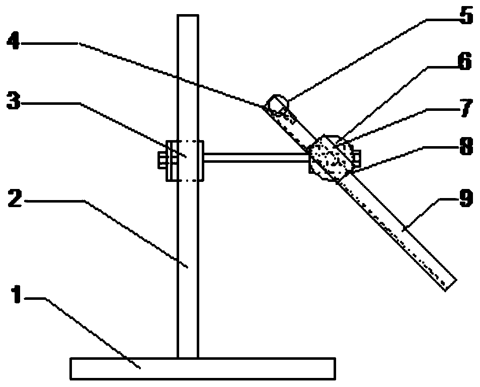
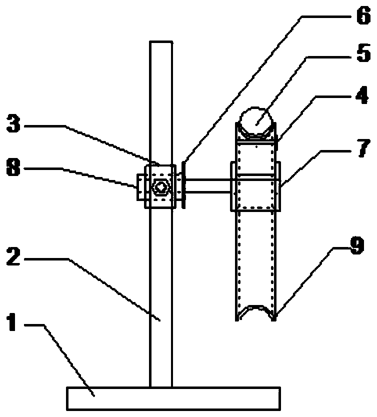
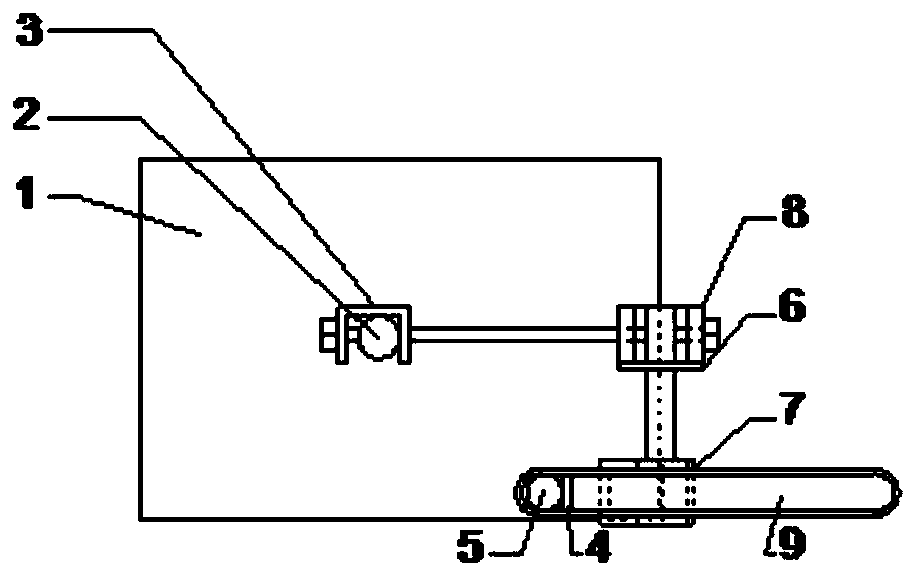
[0027] Such as Figure 1 to Figure 12 As shown, a controllable excitation device for acoustic vibration detection according to the present invention includes a support base 1, a support rod 2, a clamping device 3, a positioning pin 4, an excitation ball 5, a disc 6, a slideway fixture 7, Turn the fixture 8 and the slideway 9;

[0028] The support base 1 is provided with a support rod 2, one end of the clamping device 3 is arranged on the support rod 2, and can slide up and down along the support rod 2, the other end of the clamping device 3 is connected with the rotating fixture 8, and the slideway fixture 7 It is installed on the rotating fixture 8 through a connecting rod rotation, and the rotating fixture 8 is provided with a disc 6 near the side of the slideway fixture 7, the slideway 9 is arranged on the slideway fixture 7, and the excita...


PUM


Abstract

The invention discloses a controllable excitation device for acoustic vibration detection, which belongs to the technical field of acoustic vibration detection, and aims to solve the problem that theexcitation intensity is not easy to control due to the fact that excitation is generally applied in a knocking mode in a traditional detection method. A supporting rod is arranged on a supporting base; one end of a clamping device is arranged on the supporting rod and the clamping device can slide vertically along the supporting rod; the other end of the clamping device is connected with a rotating clamp; a slideway clamp is arranged on the rotating clamp in a rotating mode through a connecting rod; a disc is arranged on the side, close to the slideway clamp, of the rotating clamp; the slideway is arranged on the slideway clamp; and a small excitation ball is arranged in the slideway through a positioning pin. According to the controllable excitation device for acoustic vibration detection, quantitative control over the excitation intensity, angle and excitation point can be achieved, and the efficiency and the accuracy of detecting the acoustic vibration performance of a material areimproved.

Description

technical field [0001] The invention relates to an excitation device, in particular to a controllable excitation device for acoustic vibration detection, and belongs to the technical field of acoustic vibration detection. Background technique [0002] As a mature detection method, acoustic vibration detection has been widely used in scientific research and industrial production. In the acoustic vibration detection experiment, applying excitation is an essential link. The traditional method generally adopts the percussion method to apply the excitation, artificially using a hammer, a blade or a small wooden strip to knock the test piece to meet the requirements of vibration detection, but this method has great limitations. The size is not easy to control, and the strength of each tap will be different; 2. Due to the operation problem of the tester during the excitation, there will be a phenomenon of continuous tapping and tapping for too long, which will have a great impact ...

Claims


Application Information

Patent Timeline
Patent Type & Authority Applications(China)
IPC IPC(8): G01N29/04G01N29/22
CPCG01N29/045G01N29/223G01N2291/023
Inventor 刘镇波翟学勇李慕之周静张元婷
Owner NORTHEAST FORESTRY UNIVERSITY
Why Eureka
Try Eureka