Door pivot structure and intelligent logistics cabinet with door pivot structure
A shaft structure and pivot technology, applied in the field of intelligent logistics cabinets, can solve the problems of high variability of welding quality, poor pivoting of door panels, and complicated disassembly and assembly operations, so as to avoid high variability of welding quality and facilitate maintenance.
- Summary
- Abstract
- Description
- Claims
- Application Information
AI Technical Summary
Problems solved by technology
Method used
Image

Examples
Embodiment Construction
[0019] The following specific embodiments will further illustrate the present invention in conjunction with the above-mentioned drawings.
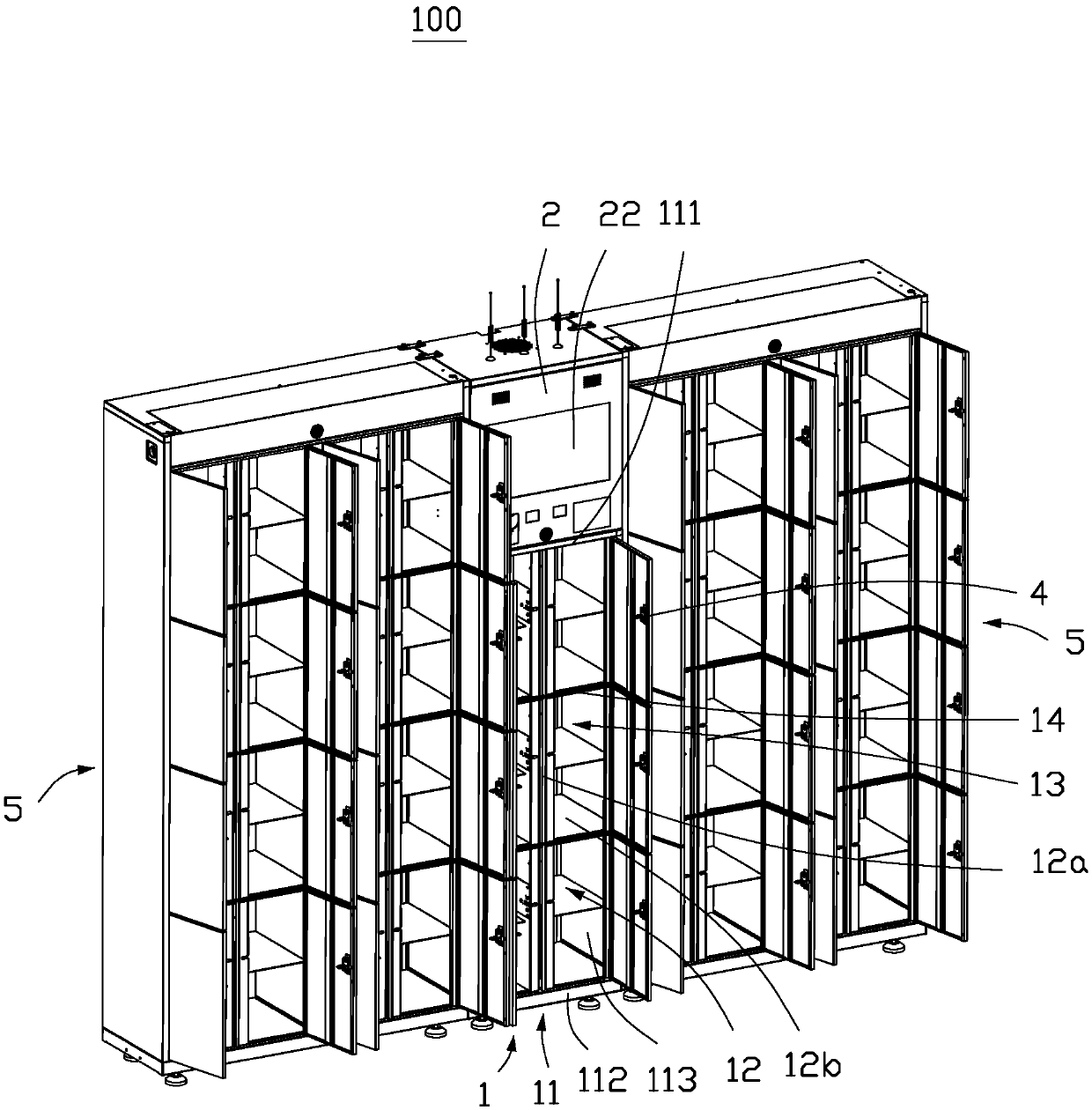
[0020] Such as figure 1 As shown, the smart logistics cabinet 100 of the embodiment of the present invention provides users with convenient delivery or collection of items. The intelligent logistics cabinet 100 of the embodiment of the present invention includes a main cabinet body 1 and a console 2 .
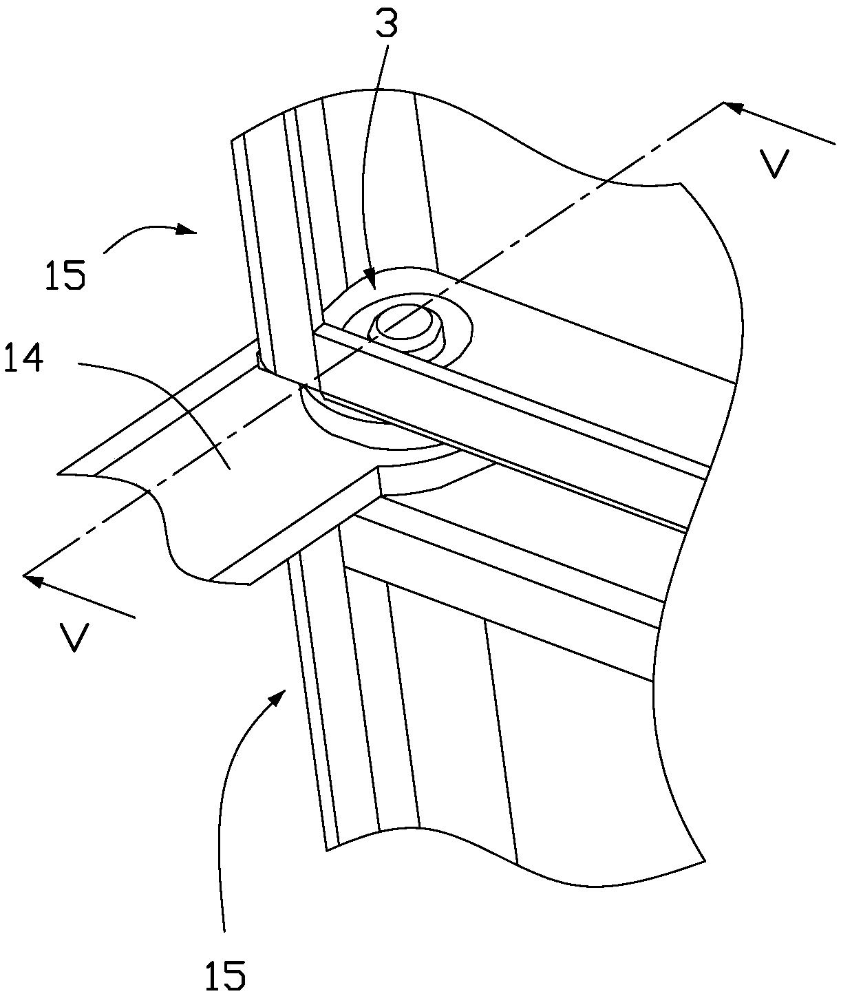
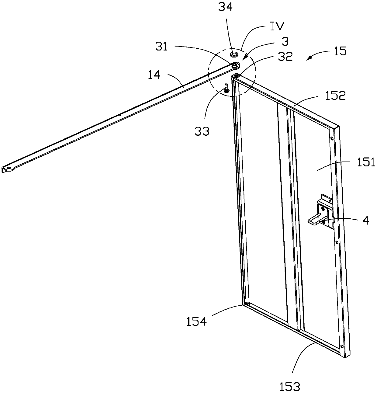
[0021] The main cabinet body 1 includes a frame body 11, and a plurality of partitions 12 are arranged inside the frame body 11 to form a plurality of storage spaces 13, and a door frame plate 14 is arranged at the opening of each storage space 13, matching figure 2 and image 3 As shown, the door panel 15 is pivotally arranged on the door frame panel 14 through the door pivot structure 3 , and the door panel 15 is provided with an electronic door lock 4 , and the door panel 15 can be locked on the door frame panel 14 through the door lo...
PUM
 Abstract
Description
Claims
Application Information