
Motor rotors and motors

A motor rotor and rotor core technology, which is applied in the direction of electromechanical devices, electrical components, electric components, etc., can solve the problems of poor output torque capacity per unit current, reduced effective utilization of motor current, etc., to ensure output torque capacity, The effect of permanent magnet torque enhancement and reduction of magnetic circuit saturation

Active Publication Date: 2021-10-22
ZHUHAI GREE REFRIGERATION TECH CENT OF ENERGY SAVING & ENVIRONMENTAL PROTECTION
View PDF0 Cites 0 Cited by
  • Summary
  • Abstract
  • Description
  • Claims
  • Application Information

AI Technical Summary

Problems solved by technology

[0002] The permanent magnet assisted synchronous reluctance motor makes full use of the reluctance torque and achieves a power density and efficiency similar to that of the rare earth permanent magnet synchronous motor; however, the permanent magnet assisted synchronous reluctance motor with a traditional structure Reluctance torque, the motor must work in a field-weakening state; when the direct-axis current of the motor is used for field-weakening, it will not generate permanent magnet torque, so the effective utilization rate of the motor current is reduced, and the output torque capacity per unit current is poor

Method used


Image

  • Motor rotors and motors
  • Motor rotors and motors
  • Motor rotors and motors

Examples


Embodiment Construction

[0026] The electromagnetic torque formula of permanent magnet assisted synchronous reluctance motor is as follows:

[0027] T e =p(L d -L q ) i d i q +pψ PM i q

[0028] Among them, p is the number of pole pairs of the motor, Ld is the direct axis of the motor, Lq is the quadrature axis inductance, id and iq are the components of the stator current space vector on the quadrature axis, ψPM is the flux linkage generated by the permanent magnet; the traditional permanent magnet assisted synchronous reluctance Motor Ld

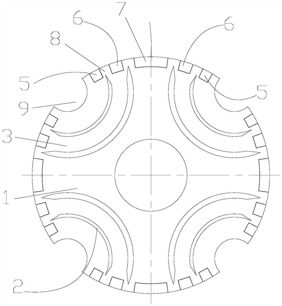
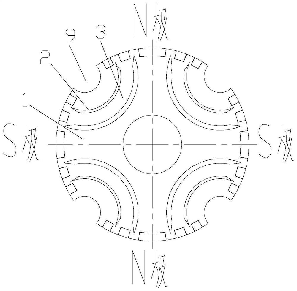
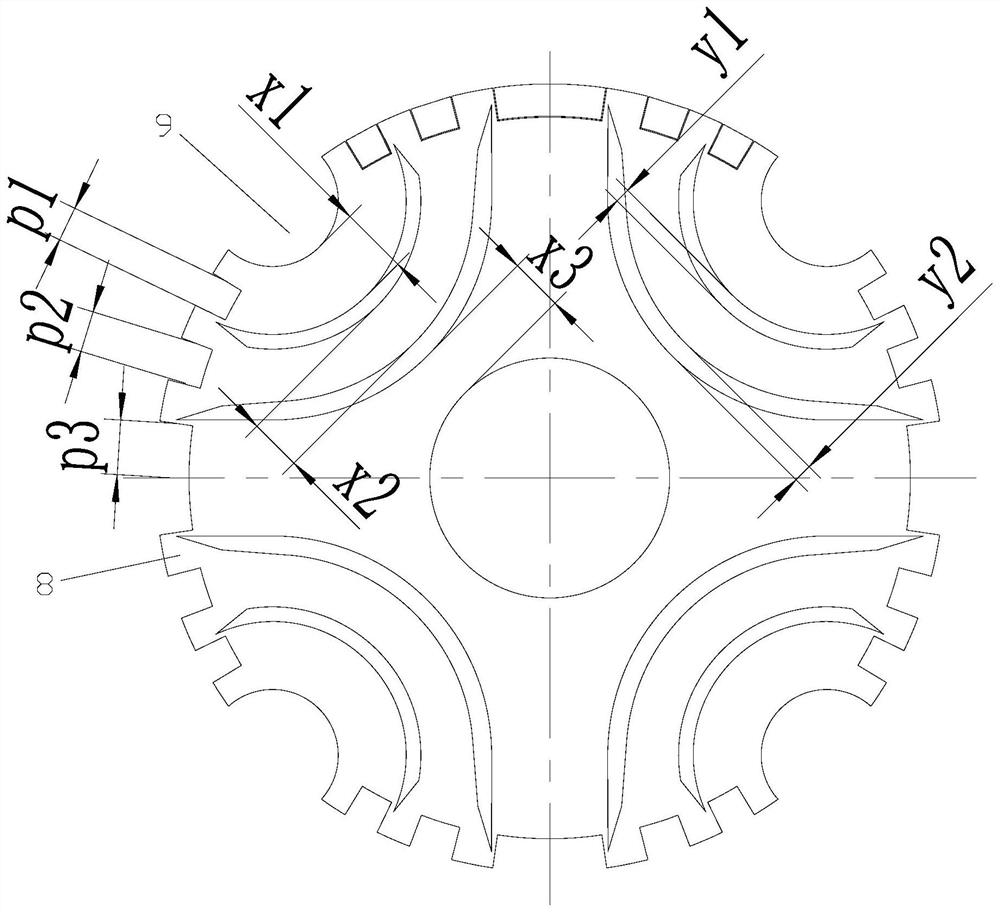
[0029] see in conjunction Figure 1 to Figure 5 As shown, according to the embodiment of the present application, the motor rotor includes a rotor core 1 and a plurality...


PUM


Abstract

The present application provides a motor rotor and a motor. The motor rotor includes a rotor core (1) and a plurality of magnetic barrier groups arranged along the circumference of the rotor core (1), and each magnetic barrier group includes a plurality of magnetic flux barriers (2) arranged in the radial direction , a magnetic conduction channel (3) is formed between two adjacent magnetic flux barriers (2), and permanent magnets are arranged at both ends of the magnetic conduction channel (3). There is the following relationship between the magnetic channels (3) on the radially outer side of the barrier (2) and the permanent magnets at their ends: p=(0.4~0.6)x, where x is the radial direction of the magnetic channel (3) Width, p is the circumferential width of the permanent magnet corresponding to the magnetic conduction channel (3). According to the motor rotor of the present application, the motor can be operated in a magnetized state, effectively reducing the degree of saturation of the magnetic circuit, and ensuring the output torque capability of the inverse salient pole permanent magnet assisted synchronous reluctance motor.

Description

technical field [0001] The present application relates to the field of motor technology, in particular to a motor rotor and a motor. Background technique [0002] The permanent magnet assisted synchronous reluctance motor makes full use of the reluctance torque, and achieves a power density and efficiency similar to that of the rare earth permanent magnet synchronous motor; however, the permanent magnet assisted synchronous reluctance motor with a traditional structure Reluctance torque, the motor must work in a field-weakening state; when the direct-axis current of the motor is used for field-weakening, it will not generate permanent magnet torque, so the effective utilization rate of the motor current is reduced, and the output torque capacity per unit current is poor . Contents of the invention [0003] Therefore, the technical problem to be solved in this application is to provide a motor rotor and motor, which can make the motor run in a state of magnetization, effec...

Claims


Application Information

Patent Timeline
Patent Type & Authority Patents(China)
IPC IPC(8): H02K1/27H02K1/28
CPCH02K1/2706H02K1/28H02K2201/03H02K2213/03
Inventor 朱晓光陈华杰周博张辉徐培荣刘进超
Owner ZHUHAI GREE REFRIGERATION TECH CENT OF ENERGY SAVING & ENVIRONMENTAL PROTECTION
Learn More