
Self-starting permanent magnet auxiliary synchronous reluctance motor rotor and motor

A technology for assisting synchronous and reluctance motors, applied in the field of motors, can solve problems such as insufficient torque output capacity and small permanent magnet torque, and achieve improved anti-demagnetization ability, increased permanent magnet torque, and increased permanent magnet magnetism. chain effect

Active Publication Date: 2022-02-25
GREE ELECTRIC APPLIANCES INC
View PDF4 Cites 0 Cited by
  • Summary
  • Abstract
  • Description
  • Claims
  • Application Information

AI Technical Summary

Problems solved by technology

[0004] Therefore, the technical problem to be solved by the present invention is to overcome the defect that the permanent magnet torque of the self-starting permanent magnet assisted synchronous reluctance motor in the prior art is relatively small, resulting in insufficient torque output capacity, thereby providing a self-starting permanent magnet synchronous reluctance motor. Magnetic Assisted Synchronous Reluctance Motor Rotor and Motor

Method used


Image

  • Self-starting permanent magnet auxiliary synchronous reluctance motor rotor and motor
  • Self-starting permanent magnet auxiliary synchronous reluctance motor rotor and motor
  • Self-starting permanent magnet auxiliary synchronous reluctance motor rotor and motor

Examples


Embodiment approach 2

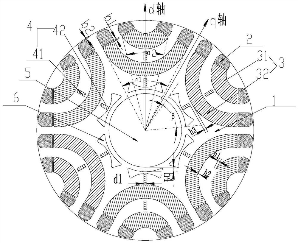
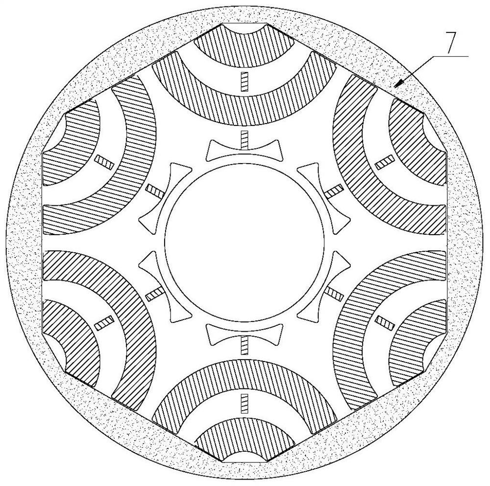
[0074] Figure 4 Shown is a structural diagram of the rotor punching according to the second embodiment of the present invention. As shown in the figure, the NdFeB is only arranged between the ferrite layers. This arrangement can not only increase the flux linkage in the q-axis direction, increase the salient pole ratio, enhance the torque output capability, but also reduce the NdFeB as much as possible. The amount of iron boron is used to reduce material costs; since the inner layer of NdFeB is eliminated, there is no need to open magnetic isolation holes, thereby greatly increasing the safety of the rotor mechanical structure. The rotor structure described can also be used for 2-pole motors or multi-pole motors. Adopting this technical solution can achieve the same technical effect as that of the first embodiment.


PUM


Abstract

The invention provides a self-starting permanent magnet auxiliary synchronous reluctance motor rotor and a motor. The self-starting permanent magnet auxiliary synchronous reluctance motor rotor comprises a plurality of rotor punching sheets, wherein the plurality of rotor punching sheets are laminated to form a rotor core, and permanent magnets are arranged on the rotor punching sheets; and the permanent magnets comprise an outer permanent magnet relatively located on the radial outer side, an inner permanent magnet relatively located on the radial inner side and a third permanent magnet, a coercive force of the outer permanent magnet and a coercive force of the inner permanent magnet are equal and both smaller than acoercive force of the third permanent magnet, the third permanent magnet is located on a d axis of the motor rotor, and a magnetizing direction of the third permanent magnet is tangential magnetizing. According to the self-starting permanent magnet auxiliary synchronous reluctance motor rotor, the permanent magnet flux linkage of the motor can be effectively increased, the permanent magnet torque of the motor can be improved, magnetic flux is provided for the q-axis magnetic circuit of the motor rotor, the salient pole difference of the motor is further increased, the reluctance torque of the motor is fully utilized, and the torque output capability of the motor is further improved.

Description

technical field [0001] The invention relates to the technical field of motors, in particular to a self-starting permanent magnet assisted synchronous reluctance motor rotor and motor. Background technique [0002] Self-starting permanent magnet assisted synchronous reluctance motor combines the advantages of asynchronous motor on the basis of permanent magnet assisted synchronous reluctance motor. The combined effect of resistance torque realizes efficient operation at synchronous speed. Compared with the asynchronous motor, the motor runs at synchronous speed, which eliminates the slip loss, and the overall efficiency of the motor is significantly improved; compared with the asynchronous permanent magnet synchronous motor, the permanent magnet is mostly made of cheap ferrite, and the material cost is low. However, the output torque of the self-starting permanent magnet assisted synchronous reluctance motor is the combined effect of the permanent magnet torque and the reluc...

Claims


Application Information

Patent Timeline
Patent Type & Authority Applications(China)
IPC IPC(8): H02K1/274H02K1/276H02K1/24H02K1/02H02K21/46
CPCH02K1/274H02K1/2766H02K1/2773H02K1/24H02K1/02H02K21/46H02K2201/03H02K2213/03Y02T10/64
Inventor 王杜肖勇李莹史进飞李霞张志东
Owner GREE ELECTRIC APPLIANCES INC
Learn More