
Self-starting permanent magnet auxiliary synchronous reluctance motor rotor and motor

A technology for auxiliary synchronous and reluctance motors, applied in the field of motors, can solve the problems of large demagnetization risk of permanent magnets, poor anti-demagnetization ability of motors, and small coercive force of ferrite, so as to save controller loss and improve resistance Effect of improving demagnetization ability and anti-demagnetization ability

Active Publication Date: 2022-02-25
GREE ELECTRIC APPLIANCES INC
View PDF4 Cites 2 Cited by
  • Summary
  • Abstract
  • Description
  • Claims
  • Application Information

AI Technical Summary

Problems solved by technology

[0004] Therefore, the technical problem to be solved by the present invention is to overcome the low ferrite coercive force of the self-starting permanent magnet assisted synchronous reluctance motor in the prior art, which leads to poor anti-demagnetization ability of the motor. Due to the action of the pivot reaction magnetic field, the permanent magnet has the defect that there is a great risk of demagnetization, thus providing a self-starting permanent magnet assisted synchronous reluctance motor rotor and motor

Method used


Image

  • Self-starting permanent magnet auxiliary synchronous reluctance motor rotor and motor
  • Self-starting permanent magnet auxiliary synchronous reluctance motor rotor and motor
  • Self-starting permanent magnet auxiliary synchronous reluctance motor rotor and motor

Examples


Embodiment Construction

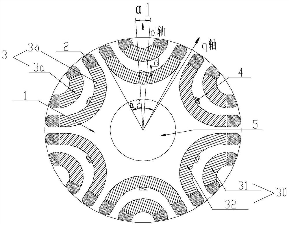
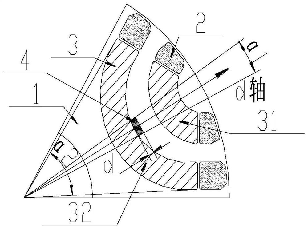
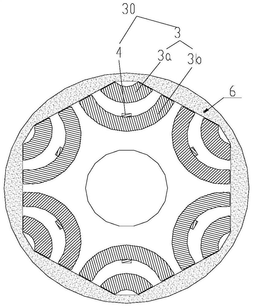
[0026] Such as Figure 1-4 As shown, the present invention provides a self-starting permanent magnet assisted synchronous reluctance motor rotor, which includes a plurality of rotor punches 1, and a plurality of rotor punches 1 are stacked to form a rotor core. There are filling slots 2, permanent magnets 30 and shaft holes 5; the permanent magnets 30 include an outer permanent magnet 31 relatively located on the radially outer side, and an inner permanent magnet 32 ​​relatively located on the radially inner side, and the outer permanent magnet 31 includes the outer layer ferrite 3a, the inner layer permanent magnet 32 ​​includes the inner layer ferrite 3b and NdFeB 4, the NdFeB 4 is located on the d-axis of the motor rotor and the NdFeB 4 is located between the outer layer ferrite 3a and the inner layer ferrite 3b. The NdFeB adopts parallel magnetization, and the magnetization direction is along the radial direction of the rotor.

[0027] In the present invention, an inner ...


PUM


Abstract

The invention provides a self-starting permanent magnet auxiliary synchronous reluctance motor rotor and a motor. The self-starting permanent magnet auxiliary synchronous reluctance motor rotor comprises a plurality of rotor punching sheets, wherein the plurality of rotor punching sheets are laminated to form a rotor core, and permanent magnets are arranged on the rotor punching sheets; and the permanent magnets comprise an outer permanent magnet relatively located on the radial outer side and an inner permanent magnet relatively located on the radial inner side, the outer permanent magnet comprises an outer-layer ferrite, the inner permanent magnet comprises an inner-layer ferrite and neodymium iron boron, and the neodymium iron boron is positioned on a d shaft of the motor rotor and is positioned between the outer-layer ferrite and the inner-layer ferrite. According to the self-starting permanent magnet auxiliary synchronous reluctance motor rotor, the flux density of the middle position of the inner-layer ferrite can be enhanced, the demagnetization resistance of the motor is improved, the permanent magnet flux linkage of the motor can be effectively increased, the permanent magnet torque of the motor is improved, the torque output capability of the motor is improved, and the operation reliability of the motor is enhanced.

Description

technical field [0001] The invention relates to the technical field of motors, in particular to a self-starting permanent magnet assisted synchronous reluctance motor rotor and motor. Background technique [0002] Self-starting permanent magnet assisted synchronous reluctance motor combines the advantages of asynchronous motor on the basis of permanent magnet assisted synchronous reluctance motor. It not only has self-starting ability, but also can run efficiently at synchronous speed. Compared with the permanent magnet assisted synchronous reluctance motor, this type of motor can realize self-starting without a controller, which reduces the cost of the motor system, and without various losses caused by the controller, the efficiency of the motor system is improved. Compared with self-starting permanent magnet synchronous motors, the permanent magnet materials of this type of motor mainly use low-cost non-rare earth permanent magnet materials, such as ferrite, etc., which gr...

Claims


Application Information

Patent Timeline
Patent Type & Authority Applications(China)
IPC IPC(8): H02K1/274H02K1/276H02K1/24H02K1/02H02K21/46
CPCH02K1/274H02K1/2766H02K1/2773H02K1/24H02K1/02H02K21/46H02K2201/03H02K2213/03Y02T10/64
Inventor 王杜肖勇李莹史进飞李霞张志东
Owner GREE ELECTRIC APPLIANCES INC
Learn More