Industrial robot tail end motion sensing device and industrial robot tail end motion sensing identification method

An industrial robot and motion sensing technology, applied in the field of robotics, to prevent fatigue damage and simplify the trajectory planning process

Active Publication Date: 2020-05-01
XI AN JIAOTONG UNIV
View PDF9 Cites 0 Cited by
  • Summary
  • Abstract
  • Description
  • Claims
  • Application Information

AI Technical Summary

Problems solved by technology

For areas where trajectory planning is difficult, the path planning process is carried out by directly pulling and guiding the robot's movement

Method used


Image

  • Industrial robot tail end motion sensing device and industrial robot tail end motion sensing identification method
  • Industrial robot tail end motion sensing device and industrial robot tail end motion sensing identification method
  • Industrial robot tail end motion sensing device and industrial robot tail end motion sensing identification method

Examples


Embodiment Construction

[0037] The present invention will be further described below in conjunction with the accompanying drawings and embodiments.

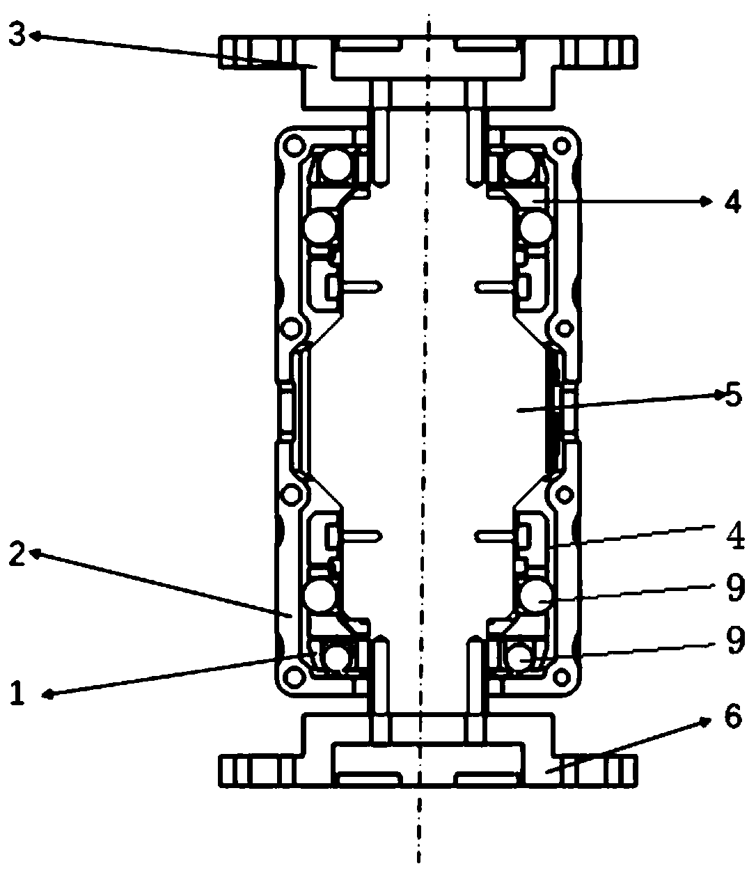
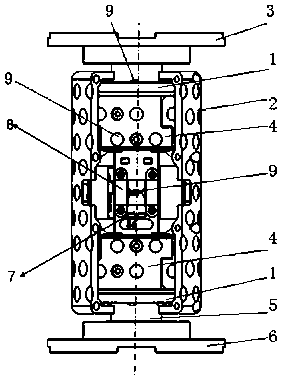
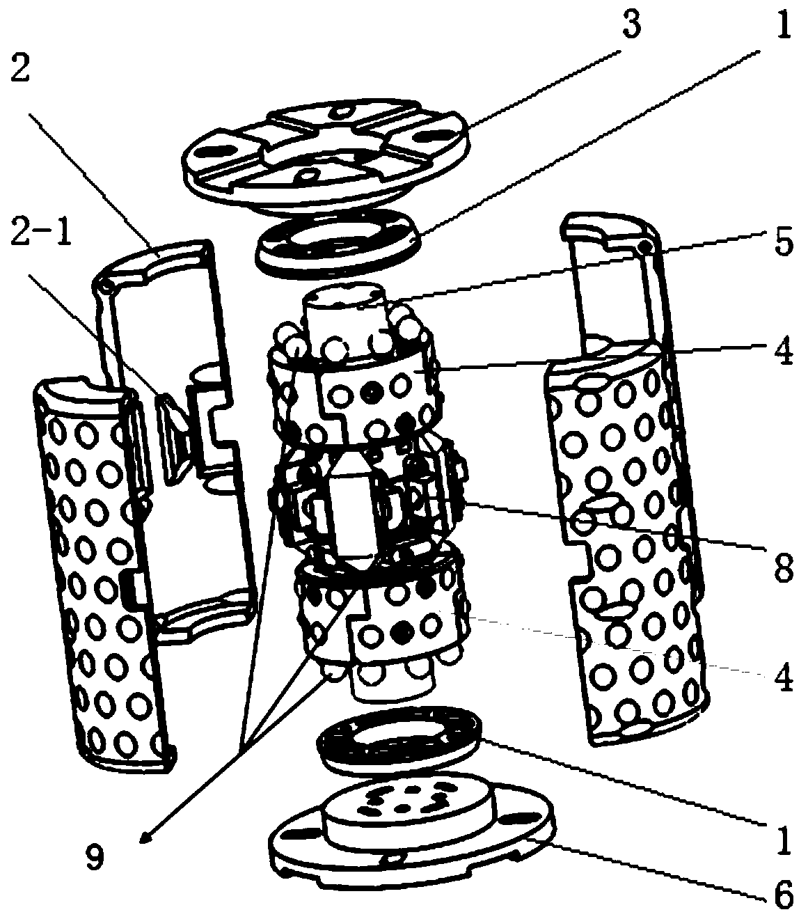
[0038] see Figure 1 ~ Figure 3 , the industrial robot terminal motion sensing device of the present invention includes a housing 2, an upper connecting flange 3, a rigid shaft 5, a lower connecting flange 6 and a flexible PCB board 7, the housing 2 is a hollow housing, and the housing 2 is set on a rigid Outside the shaft 5, the housing 2 is coaxial with the rigid shaft 5, and the two ends of the rigid shaft 5 pass through the two bottom surfaces of the housing 2 respectively, and the upper connecting flange 3 and the lower connecting flange 6 are respectively connected to the upper and lower sides of the rigid shaft 5. Both ends are rigidly connected; on the rigid shaft 5, a pressure plate is fixedly connected to the part located in the housing 2, and between the pressure plate and the housing 2, there are multiple spherical balls that can sense the s...


PUM


Abstract

The invention discloses an industrial robot tail end motion sensing device and an industrial robot tail end motion sensing identification method. The device comprises spherical sensing units, a shell,circumferential pressing plates, side pressing plates, a tail end pressing plate, a rigid shaft and a flexible PCB. Through the tail end pressing plate covering the tail end of the rigid shaft, the circumferential pressing plates arranged in a circumferential array mode and the paired mirror symmetrically arranged side pressing plates, the spherical sensing units on the device can realize accurate measurement and omnibearing sensing of six-axis micro displacement. A path planning process is carried out in a way of directly pulling and guiding a robot to move aimed at the area with the large trajectory planning difficulty, through a direct guiding mode, complex workpiece modeling steps, complex algorithm operation task slicing and the like can be directly omitted, and the trajectory planning process is remarkably simplified.

Description

technical field [0001] The invention belongs to the technical field of robots, and in particular relates to an end motion sensing device and an identification method of an industrial robot. Background technique [0002] With the advent of the fourth industrial revolution led by intelligent manufacturing, robots are widely used in the fields of automobiles and their parts, 3C industry and other fields. However, in the manufacturing process of special equipment, such as the spraying of rocket tanks, the development of industrial robots (such as spraying robots) has been severely restricted. Different from ordinary spraying objects, the rocket tank is a typical large-scale and complex structural part, and the planning of the spraying path is difficult; the tank and the industrial robot are in motion during the spraying process, and the robot is easy to collide with the tank; in order to meet the The spraying process requires the robot to be equipped with multiple and complex e...

Claims


Application Information

Patent Timeline
Patent Type & Authority Applications(China)
IPC IPC(8): B25J19/02B25J9/16
CPCB25J9/16B25J9/1664B25J19/02
Inventor 徐海波王睿刘力刘晓东
Owner XI AN JIAOTONG UNIV
Why Eureka
Try Eureka