Device for utilizing dead load of concrete to eliminate gap of continuous wall

A concrete and void technology, applied in sheet pile wall, construction, infrastructure engineering, etc., can solve the problems of fixation, unbalanced concrete injection, poor fluidity, etc.

Active Publication Date: 2020-05-01
GUANGDONG YUANTIAN ENG
View PDF3 Cites 1 Cited by
  • Summary
  • Abstract
  • Description
  • Claims
  • Application Information

AI Technical Summary

Problems solved by technology

[0003] In order to increase the strength of the continuous wall, the structure of the steel cage is relatively complicated. The traditional placement of the steel cage is only to put it into the deep groove, and it cannot be fixed to the deep groove, resulting in the process of passing the concrete material. , the impact force of the concrete will move the reinforcement cage, which will lead to the reduction of the strength of the formed continuous wall; in addition, the concrete feeding method in the prior art only uses a number of conduits to pass the concrete into the reinforcement cage, because the concrete has a certain It is viscous and has poor fluidity, which leads to uneven injection of concrete, resulting in voids that affect the quality of the wall. Therefore, a device that uses the weight of concrete to eliminate the voids in the continuous wall came into being.

Method used


Image

  • Device for utilizing dead load of concrete to eliminate gap of continuous wall
  • Device for utilizing dead load of concrete to eliminate gap of continuous wall
  • Device for utilizing dead load of concrete to eliminate gap of continuous wall

Examples


Embodiment Construction

[0027] The following will clearly and completely describe the technical solutions in the embodiments of the present invention with reference to the accompanying drawings in the embodiments of the present invention. Obviously, the described embodiments are only some, not all, embodiments of the present invention. Based on the embodiments of the present invention, all other embodiments obtained by persons of ordinary skill in the art without making creative efforts belong to the protection scope of the present invention.

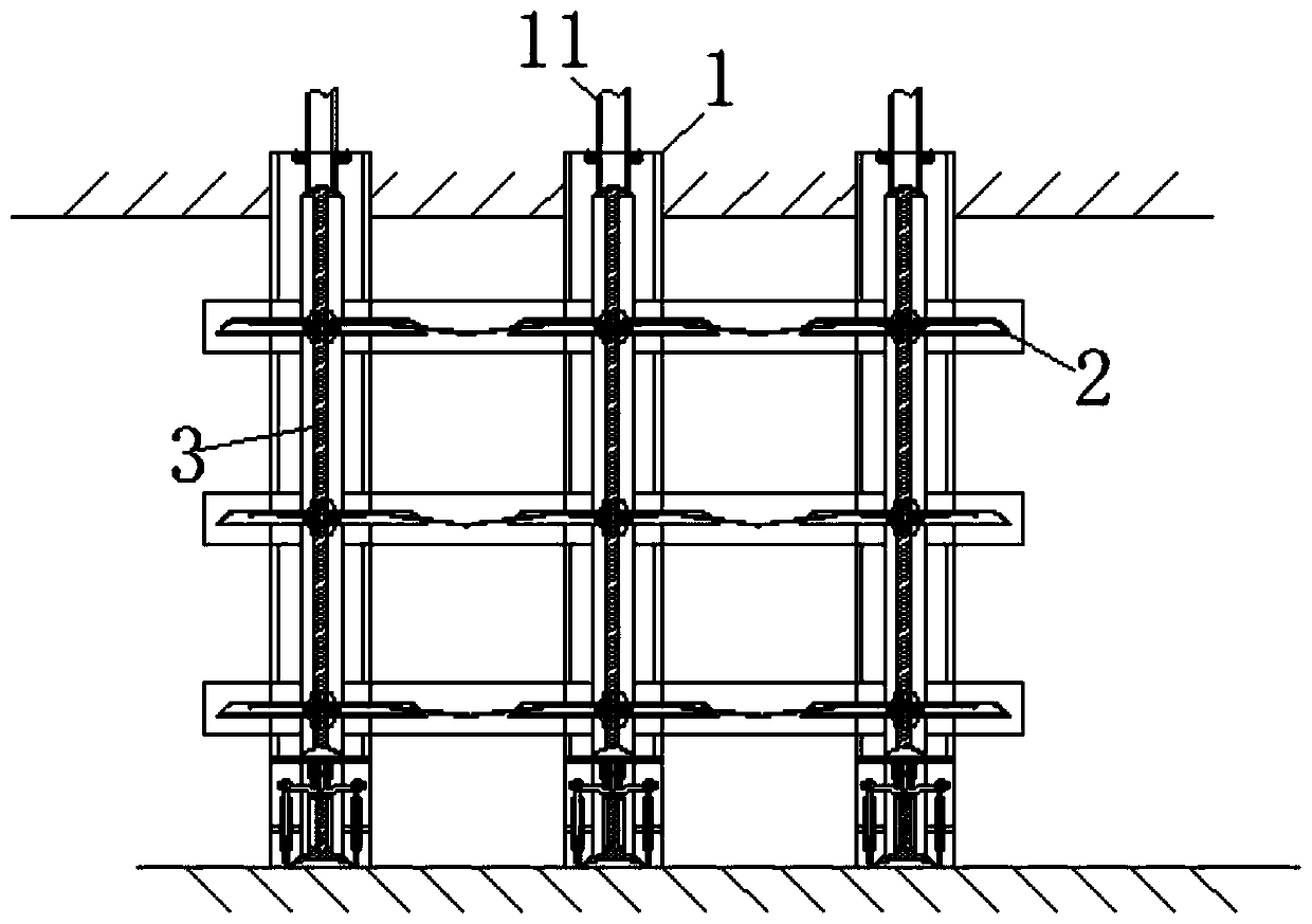
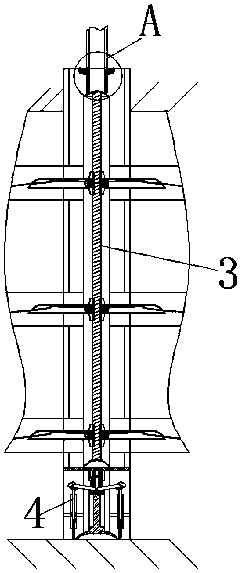
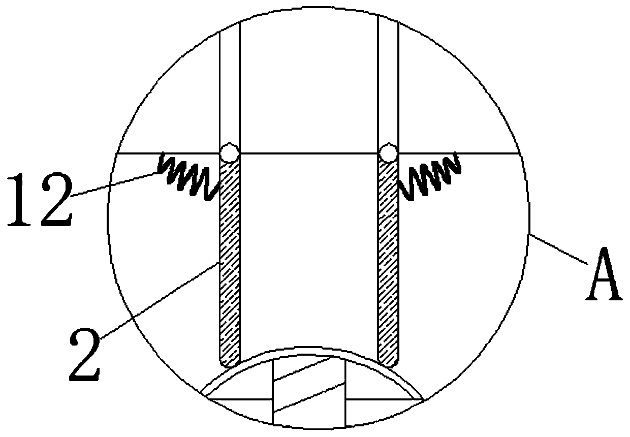
[0028] see Figure 1-11 , a device for eliminating gaps in the continuous wall by using the self-weight of concrete, including a support frame 1, the back of the support frame 1 is fixedly connected with a reinforcement cage, and the reinforcement cage will lean against the surface of the support frame 1, and the support frame 1 is placed in front of the reinforcement cage surface, and make the homogenizing plate 5 correspond to the reinforcement layer of the ...


PUM


Abstract

The invention relates to the technical field of continuous wall constructions and discloses a device for utilizing dead load of concrete to eliminate a gap of a continuous wall. The device comprises asupporting frame. Evenly mixing plates are movably connected into the supporting frame. The bottoms of the evenly mixing plates are movably connected with rotating shafts. The bottoms of the rotatingshafts are movably connected with fixing pieces. The surfaces of the rotating shafts are movably connected with homogenizing plates. The inner portions of the homogenizing plates are movably connected with gears. The inner portions of the gears are movably connected with scroll springs. The surfaces of the scroll springs are movably connected with winding rollers. Accumulation at the position ofthe evenly mixing plates facilitates homogenization of the concrete in a later period; and concrete flowing out from the surfaces of the evenly mixing plates can flow to the surfaces of the homogenizing plates, so that the rotation speed of the gears on the surfaces of the rotating shafts becomes rapider. Due to the action of the scroll springs and the multiple homogenizing plates, the flowing concrete is accumulated firstly and then flows down from the surfaces of the homogenizing plates, each accumulation gives a certain speed to the concrete, and then the effect of utilizing the weight of the concrete to feed the concrete layer by layer so as to eliminate the gap is achieved.

Description

technical field [0001] The invention relates to the technical field of diaphragm wall construction, in particular to a device for eliminating gaps in a diaphragm wall by using the self-weight of concrete. Background technique [0002] Diaphragm wall, also known as underground diaphragm wall, is a kind of grooving machine used in foundation engineering on the ground. The manufacturing process is to excavate a long and narrow deep groove along the peripheral axis of deep excavation project under the condition of mud retaining wall. Afterwards, the reinforcement cage is hoisted, and the concrete flow material is passed into it, and cooled and solidified to form an independent unit groove end. [0003] In order to increase the strength of the continuous wall, the structure of the reinforcement cage is relatively complicated. The traditional placement of the reinforcement cage is only to put it into the deep groove, and it cannot be fixed to the deep groove, resulting in the proc...

Claims


Application Information

Patent Timeline
Patent Type & Authority Applications(China)
IPC IPC(8): E02D5/20E02D15/02
CPCE02D5/20E02D15/02
Inventor 万明明
Owner GUANGDONG YUANTIAN ENG
Why Eureka
Try Eureka