Light-weight lashing bridge structure of ultra-large container ship

A container ship, super-large technology, applied in deck loading, ship accessories, transportation and packaging, etc., can solve the problems of heavy lashing bridge weight, complex installation process, large shear wall coverage, etc., to achieve weight reduction, reduce the overall Structural weight, saving effect of installation process

Inactive Publication Date: 2020-05-05
708TH RES INST OF CSSC
View PDF8 Cites 3 Cited by
  • Summary
  • Abstract
  • Description
  • Claims
  • Application Information

AI Technical Summary

Benefits of technology

This invention relates to an improved design for connecting multiple column structures within a boat's deck without adding extra materials like steel plating. It achieves this improvement through reducing the size of each part while maintaining its necessary sturdy support during use. Additionally, it eliminated the need for heavy equipment at critical points such as keys that could cause damage from impact with other boats when they are being driven over uneven surfaces. Overall, these improvements improve efficiency and reduce costs associated with building up ships.

Problems solved by technology

This patented describes various technical problem addressed in this patents: The current method used by lashers in container vessels requires multiple columns connecting them together at both ends, making assembly difficult without adding extra weights. Additionally, there may exist issues where heavier equipment needs to be installed due to its increased size.

Method used


Image

  • Light-weight lashing bridge structure of ultra-large container ship
  • Light-weight lashing bridge structure of ultra-large container ship
  • Light-weight lashing bridge structure of ultra-large container ship

Examples


Embodiment Construction

[0034] The present invention will be described in detail below in conjunction with the accompanying drawings and specific embodiments. The present invention is not limited to this embodiment, and other embodiments may also belong to the scope of the present invention as long as they conform to the gist of the present invention.

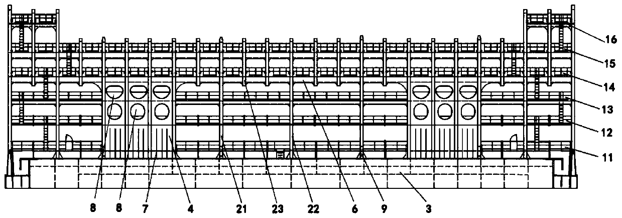
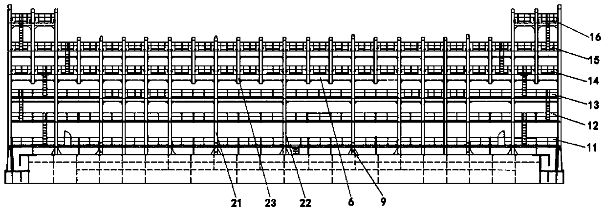
[0035] In a preferred embodiment of the present invention, based on the above-mentioned problems existing in the prior art, a lightweight lashing bridge structure for an ultra-large container ship is now provided, such as figure 1 and figure 2 shown, including:

[0036] Several horizontal platforms are arranged along the ship width direction of the ultra-large container ship, and the horizontal platforms include:

[0037] The first layer of horizontal platform 11, the first layer of horizontal platform 11 is a continuous platform between the port side and the starboard side of an ultra-large container ship;

[0038] The second layer of horizontal ...


PUM


Abstract

The invention provides a light-weight lashing bridge structure of an ultra-large container ship and relates to the technical field of ship design. The structure comprises a plurality of horizontal platforms arranged along the width direction of the ultra-large container ship, stand columns and a plurality of shear walls, wherein the stand columns are vertically arranged on two sides, in the ship length direction of the large container ship, of each horizontal platform and fixedly connected with the horizontal platforms, the stand columns comprise a plurality of cabin cover guide stand columns,a plurality of first stand columns and a plurality of second stand columns, bottom ends of the cabin cover guide stand columns are supported on a ship body cabin coaming structure of the large container ship, bottom ends of the first stand columns are supported on a ship body structure of the large container ship, bottom ends of the second stand columns are not connected with the ship body structure of the large container ship, the shear walls are arranged between the stand columns at intervals in the ship width direction, and the shear walls are longitudinally arranged between the fourth-layer horizontal platform and the ship body cabin coaming structure. The structure is advantaged in that the weight of the whole structure is reduced, and construction cost is reduced.

Description


Claims


Application Information

Patent Timeline
Owner 708TH RES INST OF CSSC
Why Eureka
Try Eureka