Movable lifting device

A lifting device and lifting frame technology, applied in the lifting device, lifting frame and other directions, can solve the problems of inconvenient operation and slow speed, and achieve the effects of high reliability, large lifting weight and fast movement.

Pending Publication Date: 2020-05-05
成都大秦民安消防科技有限公司
View PDF9 Cites 2 Cited by
  • Summary
  • Abstract
  • Description
  • Claims
  • Application Information

AI Technical Summary

Problems solved by technology

[0002] With the development of society, there are more and more vehicles. In areas such as residential areas, underground parking lots, fire exits, emergency passages, etc., there are random parking or parking problems, so it is necessary to assist in moving vehicles. Usually, it is often After being lifted by the lifting device, use a special bracket to push the vehicle to move. This method is not only slow, but also inconvenient to operate.

Method used


Image

  • Movable lifting device
  • Movable lifting device
  • Movable lifting device

Examples


Embodiment 1

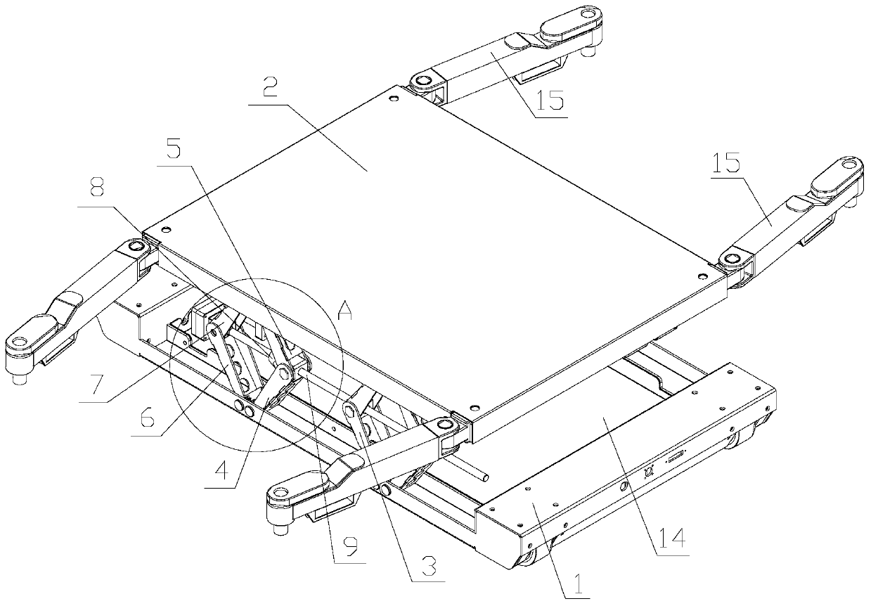
[0024] Such as figure 1 As shown, a mobile lifting device includes a freely walking chassis 1 and a pallet 2 arranged above the chassis 1. A lifting mechanism 3 is arranged between the chassis 1 and the pallet 2 to control the pallet 2 to rise or fall. The lifting mechanism 3 is provided with two groups, which are respectively located on both sides of the top surface of the chassis 1 .

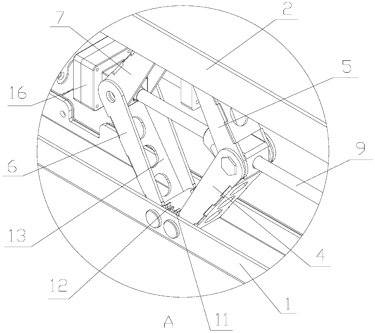
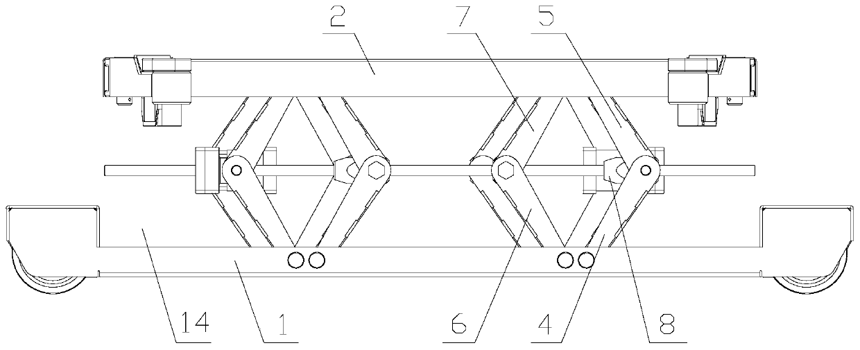
[0025] Specifically, such as Figure 1~5 As shown, the lifting mechanism 3 includes a lifting frame, a leading screw 9 and a drive motor 10, and the lifting frame includes a first lower bracket 4 and a first upper bracket 5; one end of the first lower bracket 4 rotates with the chassis 1 Connected, the other end of the first lower bracket 4 is movably connected with a lead screw nut 8, and one end of the first upper bracket 5 is rotationally connected with the first lower bracket 4, and the other end of the first upper bracket 5 is rotationally connected with the tray 2, so The above-mention...

Embodiment 2

[0029] Such as figure 1 As shown, a mobile lifting device includes a freely walking chassis 1 and a pallet 2 arranged above the chassis 1. A lifting mechanism 3 is arranged between the chassis 1 and the pallet 2 to control the pallet 2 to rise or fall. The lifting mechanism 3 is provided with two groups, which are respectively located on both sides of the top surface of the chassis 1 .

[0030] Specifically, such as Figure 1~5 As shown, the lifting mechanism 3 includes a lifting frame, a leading screw 9 and a drive motor 10, and the lifting frame includes a first lower bracket 4 and a first upper bracket 5; one end of the first lower bracket 4 rotates with the chassis 1 Connected, the other end of the first lower bracket 4 is movably connected with a lead screw nut 8, and one end of the first upper bracket 5 is rotationally connected with the first lower bracket 4, and the other end of the first upper bracket 5 is rotationally connected with the tray 2, so The above-mention...

Embodiment 3

[0035] Such as figure 1 As shown, a mobile lifting device includes a freely walking chassis 1 and a pallet 2 arranged above the chassis 1. A lifting mechanism 3 is arranged between the chassis 1 and the pallet 2 to control the pallet 2 to rise or fall. The lifting mechanism 3 is provided with two groups, which are respectively located on both sides of the top surface of the chassis 1 .

[0036] Specifically, such as Figure 1~5As shown, the lifting mechanism 3 includes a lifting frame, a leading screw 9 and a drive motor 10, and the lifting frame includes a first lower bracket 4 and a first upper bracket 5; one end of the first lower bracket 4 rotates with the chassis 1 Connected, the other end of the first lower bracket 4 is movably connected with a lead screw nut 8, and one end of the first upper bracket 5 is rotationally connected with the first lower bracket 4, and the other end of the first upper bracket 5 is rotationally connected with the tray 2, so The above-mentione...


PUM


Abstract

The invention belongs to the technical field of lifting equipment and discloses a movable lifting device. The movable lifting device comprises a chassis (1) capable of walking freely and a tray (2) arranged above the chassis (1), a lifting mechanism (3) is arranged between the chassis (1) and the tray (2) and controls the tray (2) to ascend or descend, and the lifting mechanism (3) comprises a lifting frame, a lead screw (9) and a driving motor (10). The lifting frame comprises a first lower support (4) and a first upper support (5), one end of the first lower support (4) is rotationally connected with the chassis (1), the other end of the first lower support (4) is movably connected with a lead screw nut (8), one end of the first upper support (5) is rotationally connected with the firstlower support (4), the other end of the first upper support (5) is rotationally connected with the tray (2), and the lead screw (9) is connected with the lead screw nut (8). According to the movable lifting device, rapid movement of a vehicle can be realized, the lifting weight is large, and the reliability is high.

Description

technical field [0001] The invention belongs to the technical field of lifting equipment, and in particular relates to a mobile lifting device. Background technique [0002] With the development of society, there are more and more vehicles. In areas such as residential areas, underground parking lots, fire exits, emergency passages, etc., there are random parking or parking problems, so it is necessary to assist in moving vehicles. Usually, it is often After being lifted by the lifting device, a special bracket is used to push the vehicle to move. This method is not only slow, but also inconvenient to operate. Contents of the invention [0003] In order to solve the above-mentioned problems in the prior art, the object of the present invention is to provide a mobile lifting device. [0004] The technical solution adopted in the present invention is: a mobile lifting device, including a freely walking chassis and a tray arranged above the chassis, and a lifting mechanism i...

Claims


Application Information

Patent Timeline
Patent Type & Authority Applications(China)
IPC IPC(8): B66F7/06B66F7/28
CPCB66F7/0658B66F7/28
Inventor 赵建荣冯陈强明果江波
Owner 成都大秦民安消防科技有限公司
Why Eureka
Try Eureka