Supercharge Your Innovation With Domain-Expert AI Agents!

Turbine shroud including cooling passages in communication with collection plenums

A technology of turbine shroud and cooling channel, applied in mechanical equipment, engine manufacturing, engine function, etc., can solve problems such as ineffectiveness and unavailability

Pending Publication Date: 2020-05-05
GENERAL ELECTRIC TECH GMBH
View PDF0 Cites 0 Cited by
  • Summary
  • Abstract
  • Description
  • Claims
  • Application Information

AI Technical Summary

Problems solved by technology

However, conventional impingement cooling may not be available or may be ineffective in locations of the system that require thicker walls and / or increased structure, such as near the edges of components included within the system

Method used


Image

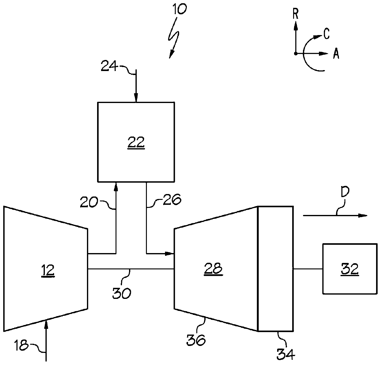
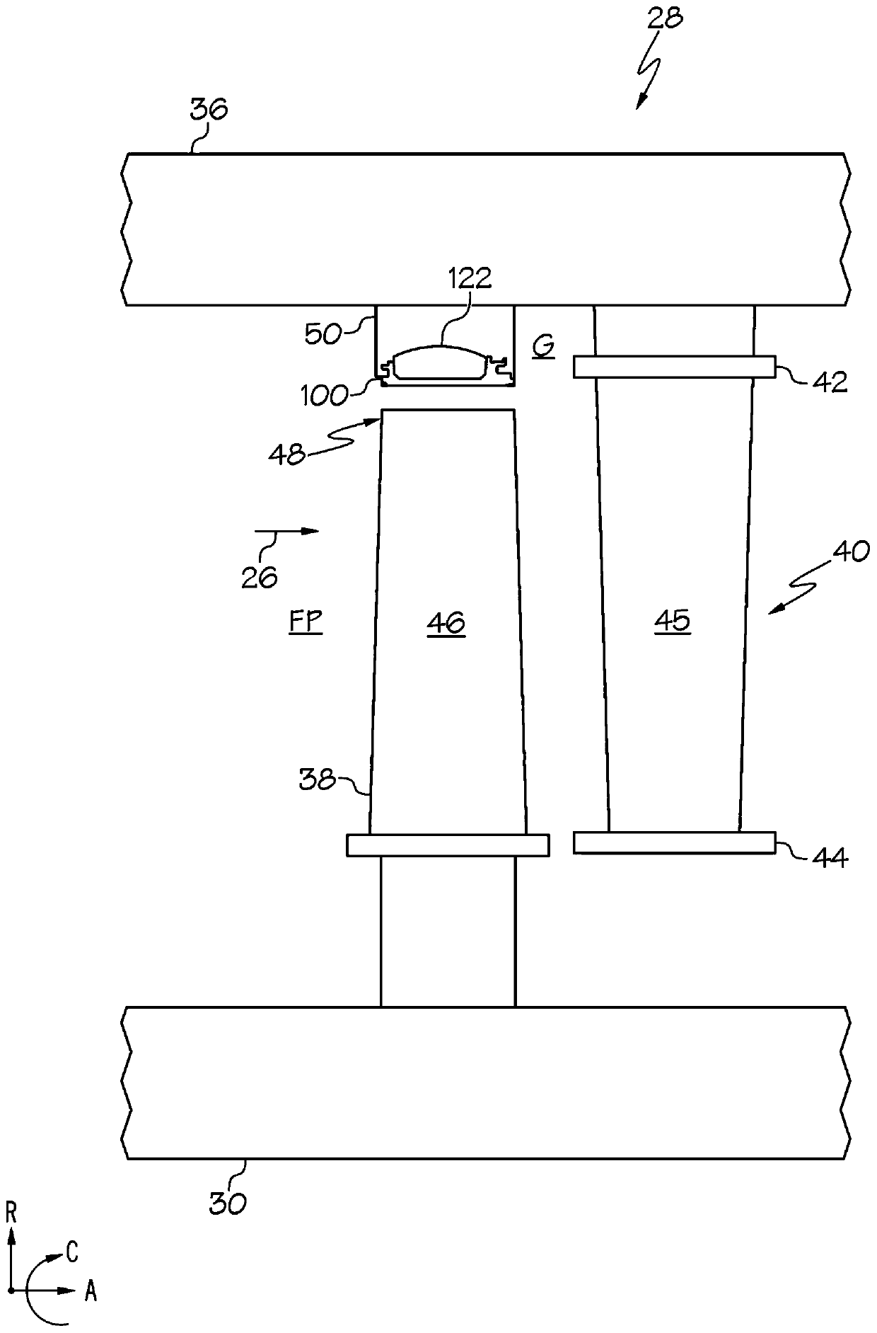
  • Turbine shroud including cooling passages in communication with collection plenums
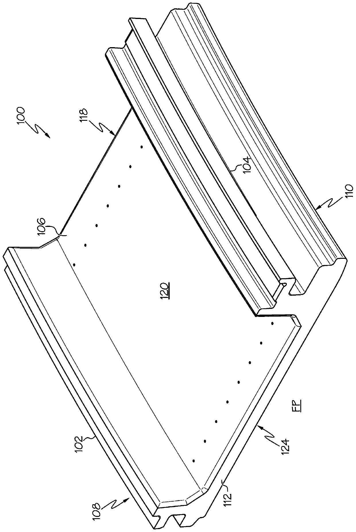
  • Turbine shroud including cooling passages in communication with collection plenums
  • Turbine shroud including cooling passages in communication with collection plenums

Examples


Embodiment Construction

[0041] First, in order to clearly describe the present disclosure, it will be necessary to select certain terms when referring to and describing relevant machine components within the scope of the present disclosure. In doing so, common industry terminology will be used and adopted, where possible, in a manner consistent with its accepted meaning. Unless otherwise indicated, such terms should be given the broadest interpretation consistent with the context of the present application and the scope of the appended claims. Those of ordinary skill in the art will appreciate that several different or overlapping terms may often be used to refer to a particular component. An object that may be described herein as a single part may comprise and be referred to in another context as consisting of multiple parts. Alternatively, an object that may be described herein as comprising multiple components may be referred to elsewhere as a single part.

[0042] In addition, several descripti...


PUM


Abstract

The invention discloses a turbine shroud including cooling passages in communication with collection plenums. Turbine shrouds (100) for turbine systems (10) are disclosed. The turbine shrouds (100) may include a forward end (108), an aft end (110), a first side (112), a second side (118), an outer surface (120) facing a cooling chamber (122) formed between the body (106) and the turbine casing (36), and an inner surface (124) facing a hot gas flow path for the turbine system (10). The turbine shroud (100) may also include at least one collection plenum extending within the body between the forward end (108) and the aft end (110). Additionally, the turbine shroud (100) may include set of cooling passage(s) (140) extending within the body (106). Each of the cooling passages (140) of the setof cooling passage(s) (140) may include an inlet portion (132) in fluid communication with the cooling chamber (122), an outlet portion (136) in fluid communication with the at least one collection plenum, and an intermediate portion (138) fluidly coupling the inlet portion (132) and the outlet portion (136).

Description

Background technique [0001] The present disclosure relates generally to turbine shrouds for turbine systems, and more particularly to turbine shrouds including a plurality of cooling passages in fluid communication with a plenum formed therein. [0002] Conventional turbines, such as gas turbine systems, are used to generate power for electrical generators. Typically, gas turbine systems generate power by passing a fluid (eg, hot gas) through turbine components of the gas turbine system. More specifically, inlet air may be drawn into the compressor and may be compressed. Once compressed, the inlet air mixes with fuel to form combustion products that may be ignited by a combustor of the gas turbine system to form the gas turbine system's operating fluid (eg, hot gas). The fluid may then flow through the fluid flow path for rotating the plurality of rotating blades and rotor or shaft of the turbine component for generating power. Fluid may be directed through the turbine comp...

Claims


Application Information

Patent Timeline
Patent Type & Authority Applications(China)
IPC IPC(8): F01D25/12F01D25/14
CPCF01D25/12F01D25/14F01D11/08F05D2240/11F05D2260/204F05D2260/202F05D2250/185F05D2230/40F05D2240/55F05D2220/32
Inventor 本杰明·保罗·拉西马修·斯科特·卢茨易卜拉欣·塞泽斯蒂芬·保罗·瓦辛格
Owner GENERAL ELECTRIC TECH GMBH
Features
  • R&D
  • Intellectual Property
  • Life Sciences
  • Materials
  • Tech Scout
  • Unparalleled Data Quality
  • Higher Quality Content
  • 60% Fewer Hallucinations
Learn More