
Kinetic Energy Harvesting Mechanism

A kinetic energy and transmission wheel technology, applied in the field of biaxial kinetic energy capture mechanism, can solve the problems of unstable direction of kinetic energy source of wind energy installations, difficulty in effectively capturing kinetic energy, etc., and achieve the effect of avoiding interference

Inactive Publication Date: 2021-04-16
SOUTHERN TAIWAN UNIVERSITY OF TECHNOLOGY +1
View PDF4 Cites 0 Cited by
  • Summary
  • Abstract
  • Description
  • Claims
  • Application Information

AI Technical Summary

Problems solved by technology

[0007] The main purpose of the present invention is to provide a kinetic energy harvesting mechanism to solve the problem that existing wind energy devices are difficult to effectively capture kinetic energy due to the unstable direction of the kinetic energy source.

Method used


Image

  • Kinetic Energy Harvesting Mechanism
  • Kinetic Energy Harvesting Mechanism
  • Kinetic Energy Harvesting Mechanism

Examples


Embodiment Construction

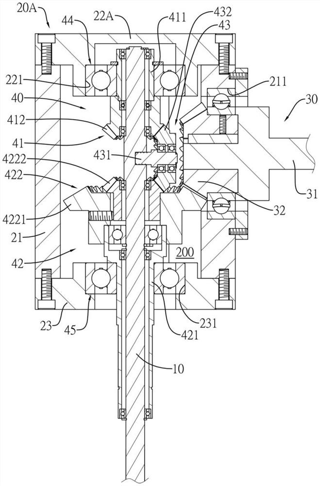
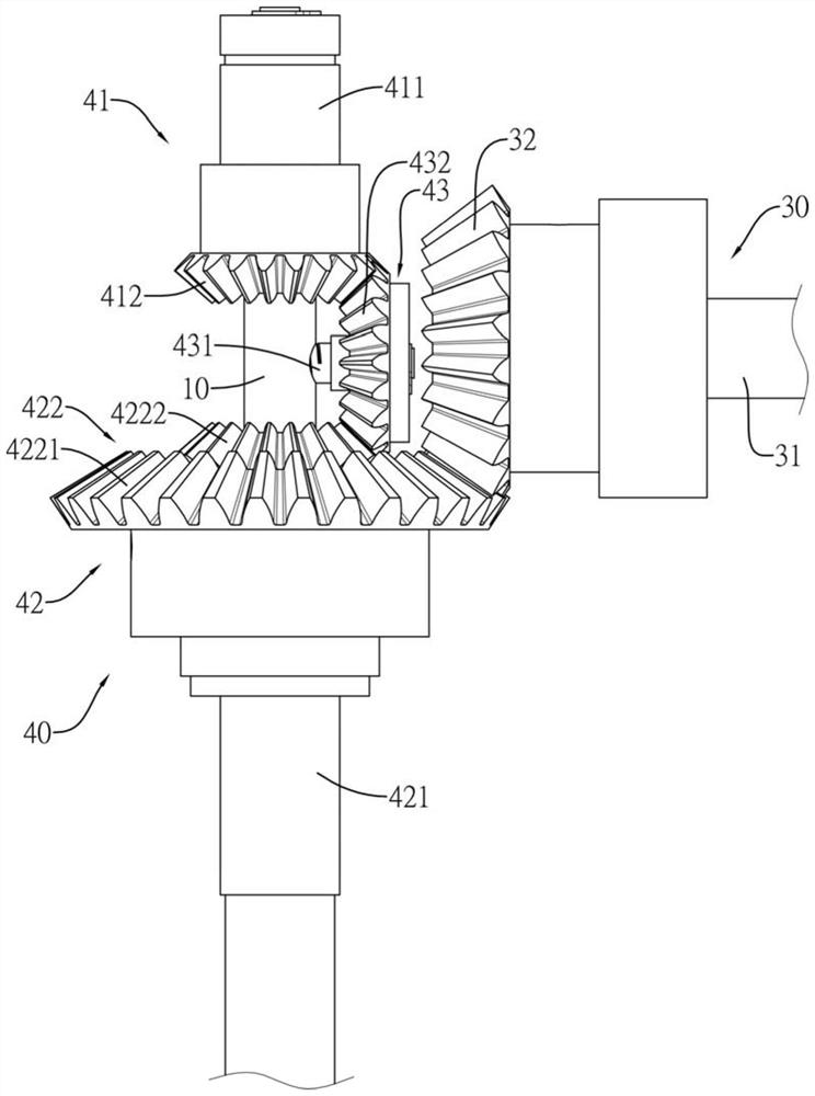
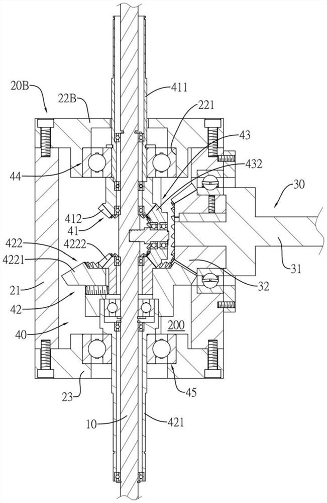
[0043] Such as Figure 1 to Figure 4 As shown, several embodiments of the kinetic energy harvesting mechanism of the present invention are disclosed. It can be seen from the drawings that the kinetic energy harvesting mechanism includes a fixed shaft 10, a rotating housing 20A, 20B, a kinetic energy input Assembly 30 and a certain shaft transmission assembly 40.

[0044] Such as Figure 1 to Figure 4 As shown, the fixed shaft 10 can be fixed upright (ie, perpendicular to the axis) to provide the necessary supporting force for the kinetic energy harvesting mechanism.

[0045] Such as Figure 1 to Figure 4 As shown, the rotating housings 20A, 20B are mounted on the fixed shaft 10, and the rotating housings 20A, 20B can rotate horizontally in a clockwise direction (from a top view) or counterclockwise with the fixed shaft 10 as the axis. The rotating housings 20A, 20B have an accommodating space 200 therein.

[0046] Such as Figure 1 to Figure 3 and Figure 4 As shown, in ...


PUM


Abstract

A kinetic energy extraction mechanism, comprising a fixed shaft, a rotating housing, a kinetic energy input assembly and a fixed shaft transmission assembly, the rotating housing can be pivotally arranged on the fixed shaft, the kinetic energy input assembly is pivotally arranged in the rotating housing and intersects the fixed shaft, The fixed shaft transmission assembly is installed in the rotating housing, the first transmission assembly of the fixed shaft transmission assembly is arranged in the rotating housing in conjunction with the first one-way bearing group, and the second transmission assembly is arranged in the rotating housing in conjunction with the second one-way bearing group Among them, the first one-way bearing and the second one-way bearing serve as counter-rotating driving functions, the third transmission component connects the first transmission component and the second transmission component to transmit motion, the first transmission component, the second transmission component and the second transmission component One of the three transmission components is connected to the kinetic energy input component to transmit the motion. Through the combined structure of two shafts in series, it is integrated into a single axis for output to continuous rotation. It is a dual-axis with 2 degrees of freedom suitable for unstable kinetic energy. Axial kinetic energy harvesting mechanism.

Description

technical field [0001] The present invention relates to a kinetic energy harvesting mechanism, in particular to a biaxial kinetic energy harvesting mechanism suitable for harvesting unstable kinetic energy. Background technique [0002] Taiwan Province is located at the junction of the Asian land and the Pacific Ocean, and is a long and narrow island terrain from north to south. There are obvious alternating monsoons every year. The annual average wind speed in Taiwan's coastal, high mountain and outlying island areas exceeds 4 meters per second, and the wind energy potential is quite large. Therefore, government units set up wind power generation equipment in many places with sufficient wind energy, and list offshore wind power generation as an important development technology in the future, in order to increase the proportion of green power generation. [0003] Among many power generation equipment, small wind power generation equipment has the advantages of small size and...

Claims


Application Information

Patent Timeline
Patent Type & Authority Patents(China)
IPC IPC(8): F03D1/00F03D15/10F03D9/25
CPCF03D1/00F03D9/25F03D15/10Y02E10/72
Inventor 瞿嘉骏王亮雄李彦益
Owner SOUTHERN TAIWAN UNIVERSITY OF TECHNOLOGY
Learn More