Nuclear energy safety pressure relief valve and position indicator device
A pressure relief valve and indicator technology, applied in the direction of valve device, valve operation/release device, valve details, etc., can solve the problem of high cost of use, the main body of the pilot safety pressure relief valve cannot directly display the valve open and close state Problems such as the location of the valve stem achieve the effects of low cost, simple and convenient assembly, and increased reliability
- Summary
- Abstract
- Description
- Claims
- Application Information
AI Technical Summary
Problems solved by technology
Method used
Image

Examples
Embodiment 1
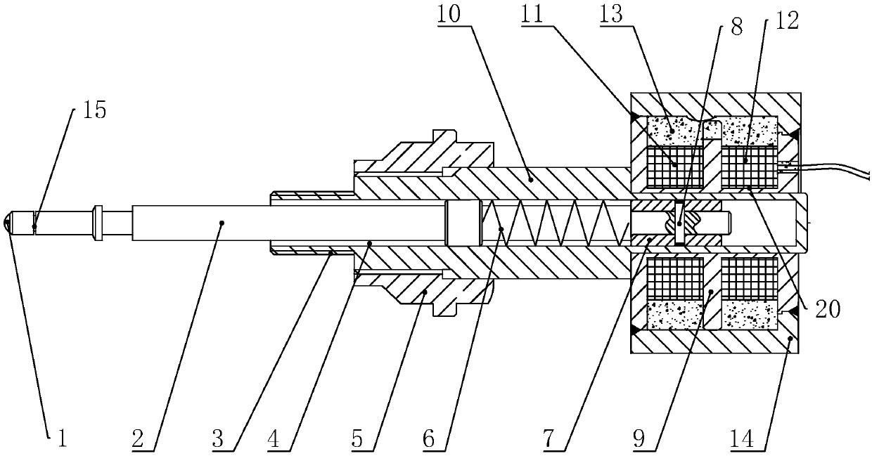
[0035] Such as figure 1 As shown, a nuclear energy safety pressure relief valve position indicator device includes a housing 10. A sliding chamber 4 with an open end is arranged inside the housing 10. A guide rod 2 is arranged in the sliding chamber 4. Between the sliding chamber 4 and the guide rod 2 An elastic member 6 is provided, and a differential inductive displacement sensor is provided at the opening end of the casing 10 away from the sliding chamber 4. In this embodiment, the elastic member 6 is a spring, and one end of the spring is connected to the inner wall of the sliding chamber 4, and the other end is connected to the guide rod 2 , when the valve stem 17 in the safety valve moves, it will drive the guide rod 2 to move. At this time, the differential inductive displacement sensor will detect the signal of the movement of the guide rod 2, and then judge whether the safety valve is opened.
[0036] When in use, one end of the guide rod 2 protrudes out of the housing ...
Embodiment 2
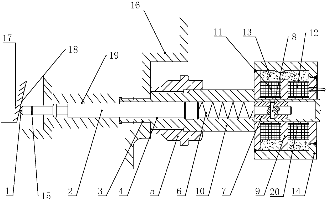
[0044] Such as figure 2 As shown, a nuclear energy safety pressure relief valve includes Embodiment 1, and also includes a safety valve body. The safety valve body includes a housing 16 and a valve stem 17 arranged in the housing 16. The valve stem 17 is provided with an inclined surface 18. , the inclined surface 18 is set at an acute angle with the central axis of the valve stem 17, and a through hole 19 is arranged on one side of the housing 16. The housing 10 is located at the opening end of the sliding chamber 4 and connected in the through hole 19, and the guide rod 2 is located outside the sliding chamber 4. One end is in conflict with the inclined surface 18 .
[0045] When in use, a through hole 19 is opened on the housing 16 along the axial direction perpendicular to the valve stem 17, and then the end of the housing 10 is inserted into the through hole 19 and the locking thread 3 is matched with the inner wall of the through hole 19. The guide rod 2 positioned in ...
PUM
 Abstract
Description
Claims
Application Information
 - R&D Engineer
- R&D Manager
- IP Professional
- Industry Leading Data Capabilities
- Powerful AI technology
- Patent DNA Extraction
Browse by: Latest US Patents, China's latest patents, Technical Efficacy Thesaurus, Application Domain, Technology Topic.
© 2024 PatSnap. All rights reserved.Legal|Privacy policy|Modern Slavery Act Transparency Statement|Sitemap