Optical imaging lens

An optical imaging lens and imaging technology, applied in the lens field, can solve the problems of low relative illumination at the edge of the imaging surface, low pixel value, blue-purple fringe, etc., and achieve good image color reproduction, high unit pixel ratio, and uniform relative illumination Effect

Pending Publication Date: 2020-05-05
XIAMEN LEADING OPTICS
View PDF0 Cites 0 Cited by
  • Summary
  • Abstract
  • Description
  • Claims
  • Application Information

AI Technical Summary

Problems solved by technology

However, the optical imaging lenses currently used in intelligent transportation systems have a low ratio of unit pixels (pixels), which is not conducive to the development of later algorithms; the general light transmission is relatively small, and the relative illuminance at the edge of the imaging surface is low; the size of the image surface (i.e. Diagonal length) is about 1 / 1.8 inch and 1 inch, which are relatively small, and the total pixel value is low; the general color difference optimization is insufficient, and blue-purple fringing is prone to occur, which can no longer meet the increasing requirements of intelligent transportation systems. Improve

Method used


Image

  • Optical imaging lens
  • Optical imaging lens
  • Optical imaging lens

Examples


Embodiment 2

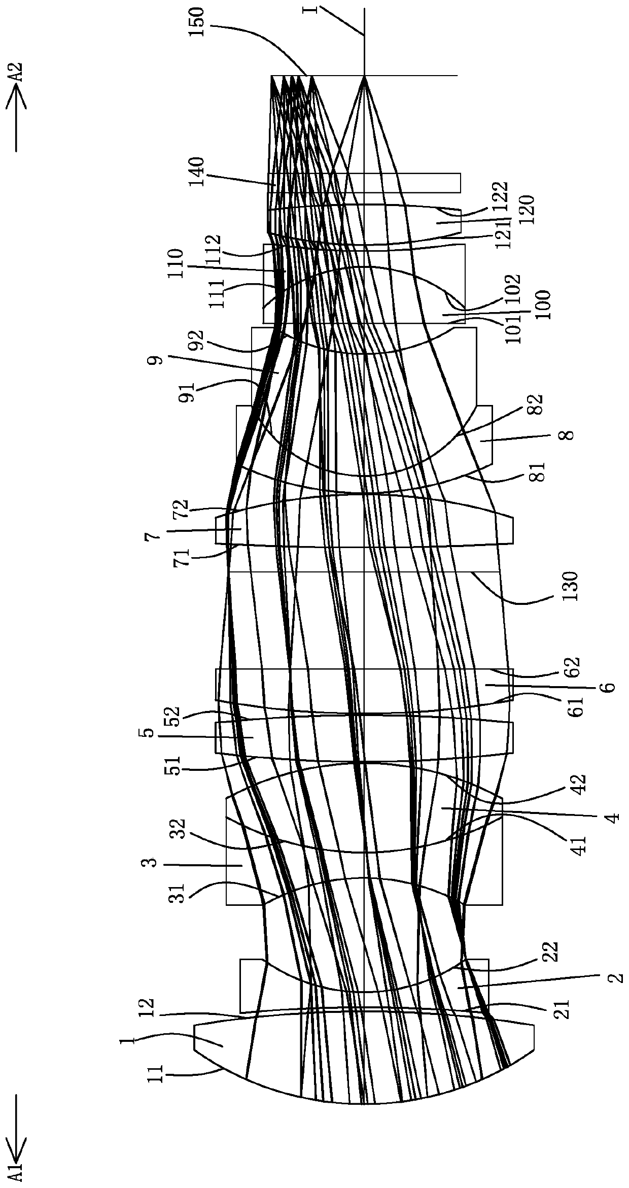
[0103] Such as Figure 7 As can be seen, the concave-convex surface and refractive index of each lens in this embodiment and the first embodiment are the same, and only the optical parameters such as the radius of curvature of the lens surface and the thickness of the lens are different.

[0104] The detailed optical data of this specific embodiment are shown in Table 2-1.

[0105] Detailed optical data of Table 2-1 Example 2

[0106]

[0107]

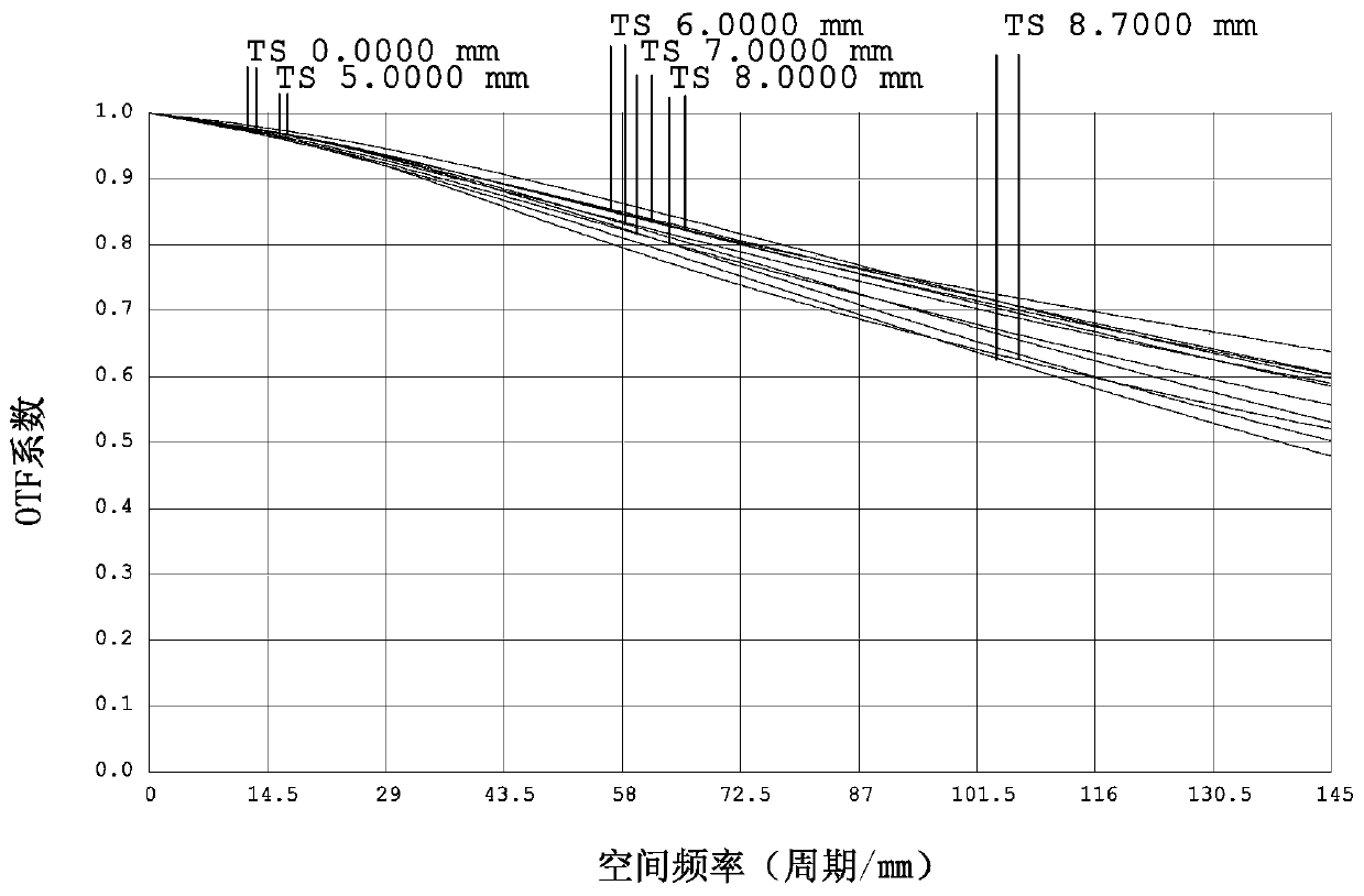
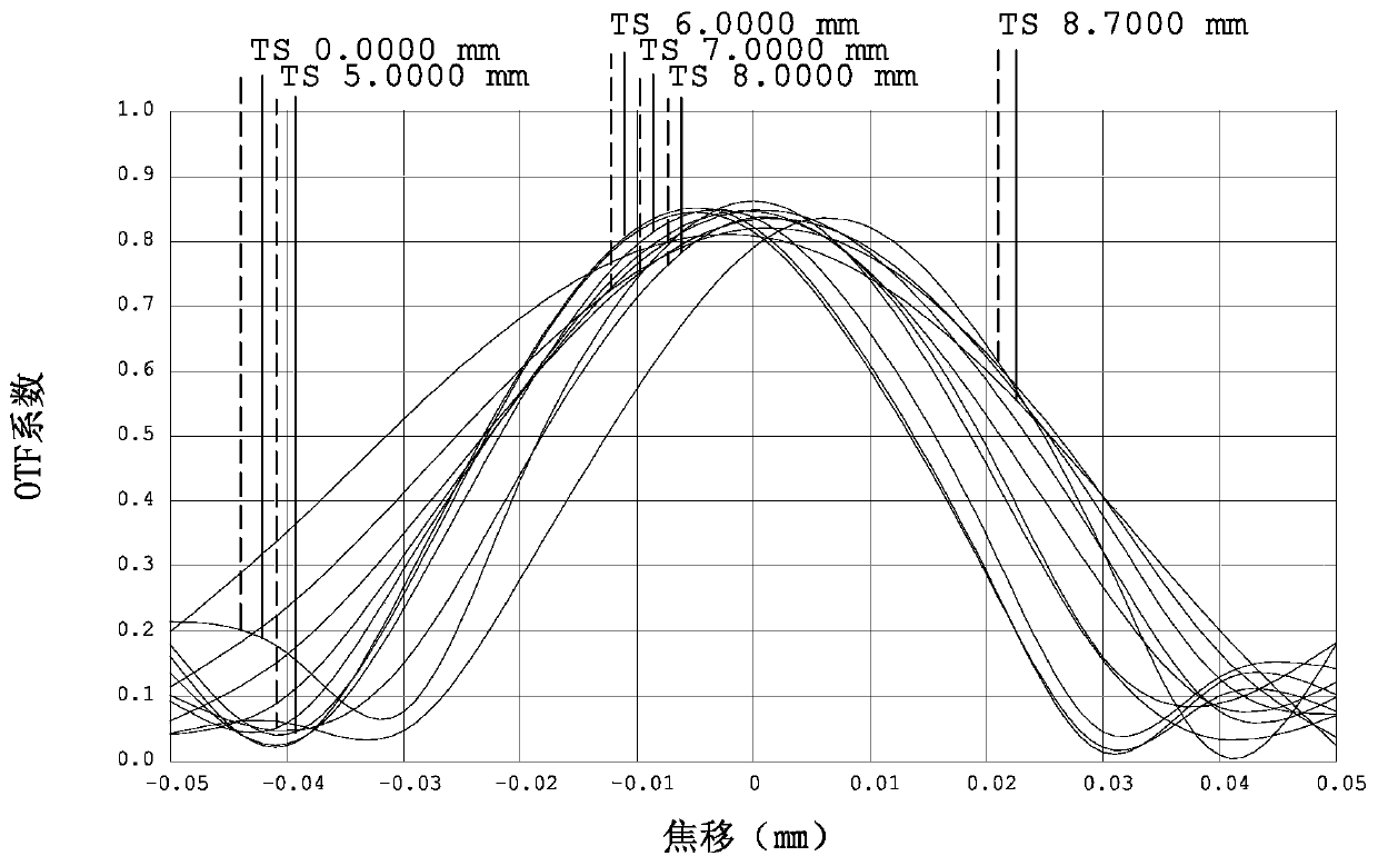
[0108] For the MTF curve of visible light in this specific embodiment, please refer to Figure 8 , it can be seen from the figure that the unit pixel ratio is high. Under the visible light environment, the MTF value at the spatial frequency of 145lp / mm is greater than 0.4, which meets the requirements of picture definition; for the defocus curve of visible light, please refer to Figure 9 , it can be seen that the image quality is uniform; for the relative illuminance of visible light, please refer to Figure 10 , it can be se...

Embodiment 3

[0111]Such as Figure 13 As shown, the surface concave-convex and refractive power of each lens in this embodiment and the first embodiment are approximately the same, only the image side 12 of the first lens 1 is a concave surface, the object side 21 of the second lens 2 is a convex surface, and the seventh lens The object side surface 71 of 7 is a concave surface, and the optical parameters such as the radius of curvature and lens thickness of each lens surface are also different.

[0112] The detailed optical data of this specific embodiment are shown in Table 3-1.

[0113] Detailed optical data of the third embodiment of table 3-1

[0114]

[0115]

[0116] For the MTF curve of visible light in this specific embodiment, please refer to Figure 14 , it can be seen from the figure that the unit pixel ratio is high. Under the visible light environment, the MTF value at the spatial frequency of 145lp / mm is greater than 0.4, which meets the requirements of picture clari...

Embodiment 4

[0119] Such as Figure 19 As shown, the surface concave-convex and refractive power of each lens in this embodiment and the first embodiment are approximately the same, only the image side 12 of the first lens 1 is a concave surface, the object side 21 of the second lens 2 is a convex surface, and the seventh lens The object side surface 71 of 7 is a concave surface, and the optical parameters such as the radius of curvature and lens thickness of each lens surface are also different.

[0120] The detailed optical data of this specific embodiment are shown in Table 4-1.

[0121] Table 4-1 Detailed optical data of Example 4

[0122]

[0123]

[0124] For the MTF curve of visible light in this specific embodiment, please refer to Figure 20 , it can be seen from the figure that the unit pixel ratio is high. Under the visible light environment, the MTF value at the spatial frequency of 145lp / mm is greater than 0.4, which meets the requirements of picture clarity; for the d...


PUM


Abstract

The invention relates to the technical field of lenses, and discloses an optical imaging lens. The optical imaging lens comprises twelve lenses, a first lens element with positive refractive index hasa convex object-side surface, a second lens element with negative refractive index has a concave image-side surface, a third lens and an eleventh lens are concave lenses with negative refractive indexes, a fourth lens, a fifth lens and a twelfth lens are convex lenses with positive refractive indexes, a sixth lens is a convex flat lens with positive refractive index, a seventh lens has positive refractive index and the image side surface is a convex surface, an eighth lens is a convex-concave lens with negative refractive index, a ninth lens is a convex-concave lens with positive refractive index, a tenth lens is a flat convex lens with positive refractive index, and the third lens and the fourth lens are glued with each other; the eighth lens and the ninth lens are glued with each other;and the tenth lens and the eleventh lens are glued with each other. The optical imaging lens has the advantages of the large image surface, the high unit pixel ratio, large light transmission, good chromatic aberration optimization and good imaging quality.

Description

technical field [0001] The invention belongs to the field of lens technology, and in particular relates to an optical imaging lens used in an intelligent traffic system. Background technique [0002] With the continuous advancement of science and technology and the continuous development of society, optical imaging lenses have also developed rapidly in recent years, and are widely used in smart phones, tablet computers, video conferencing, vehicle monitoring, security monitoring, intelligent transportation systems, etc. Therefore, the requirements for optical imaging lenses are getting higher and higher. [0003] In intelligent transportation systems, the performance of optical imaging lenses is critical and will affect the reliability of the entire system. However, the optical imaging lenses currently used in intelligent transportation systems have a low ratio of unit pixels (pixels), which is not conducive to the development of later algorithms; the general light transmis...

Claims


Application Information

Patent Timeline
Patent Type & Authority Applications(China)
IPC IPC(8): G02B13/00G02B1/00
CPCG02B1/00G02B13/00
Inventor 张军光黄波
Owner XIAMEN LEADING OPTICS
Why Eureka
Try Eureka