Large-light-flux high-resolution flight time measuring lens

A time-of-flight, high-resolution technology, applied in the field of lenses, can solve the problems of large overall size of high-resolution time-of-flight measurement lenses, large sacrifice of illuminance at the edge of the field of view, and not reaching the ideal light transmission value, so as to shorten the total length of the system and improve the Signal utilization and good control

Pending Publication Date: 2021-08-10
XIAMEN LEADING OPTICS
View PDF0 Cites 0 Cited by
  • Summary
  • Abstract
  • Description
  • Claims
  • Application Information

AI Technical Summary

Problems solved by technology

[0003] 1. The mainstream light transmission of TOF lenses in the current market is far from the ideal light transmission value required by the application
[0004] 2. TOF lenses in the current market have poor distortion control, and correction of distortion leads to a large number of pixel losses
[0005] 3. The TOF in the current market sacrifices a lot for the relative illuminance of the peripheral field of view in order to achieve a large customs clearance, and the illuminance changes greatly.
[0007] 5. The overall size of TOF and high-resolution time-of-flight measurement lenses in the current market is relatively large, and there is a gap with market demand

Method used


Image

  • Large-light-flux high-resolution flight time measuring lens
  • Large-light-flux high-resolution flight time measuring lens
  • Large-light-flux high-resolution flight time measuring lens

Examples


Embodiment 1

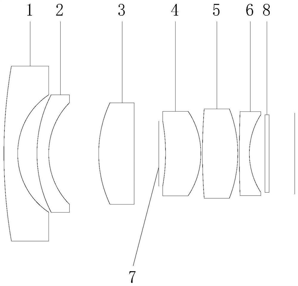
[0094] refer to figure 1 As shown, this embodiment discloses a Datong optical high-resolution time-of-flight measurement lens, which includes a first lens 1 to a sixth lens 6 along an optical axis from the object side to the image side; the first lens 1 to the sixth lens The lenses 6 each include an object side facing the object side and allowing the imaging light to pass through, and an image side facing the image side and allowing the imaging light to pass through;

[0095] The first lens 1 has a negative diopter, the object side of the first lens 1 is convex, and the image side is concave;

[0096] The second lens 2 has a negative diopter, the object side of the second lens 2 is convex, and the image side is concave;

[0097] The third lens 3 has a positive diopter, the object side of the third lens 3 is convex, and the image side is convex or flat;

[0098] The fourth lens 4 has a positive diopter, the object side of the fourth lens 4 is concave, and the image side is co...

Embodiment 2

[0110] Cooperate Figure 6 to Figure 10 As shown, the concave-convex surface and refractive index of each lens in this embodiment and the first embodiment are roughly the same, and the optical parameters such as the radius of curvature of the lens surface and the thickness of the lens are different.

[0111] The detailed optical data of this specific embodiment is shown in Table 2.

[0112] The detailed optical data of table 2 embodiment two

[0113]

[0114]

[0115] In this specific embodiment, the fourth lens 4 adopts a glass aspheric lens, and the detailed data of the parameters of the aspheric surface of the fourth lens 4 please refer to the following table:

[0116] Surface serial number K A4 A6 A8 A10 A12 A14 S8 1.09E+02 -1.42E-02 1.00E-03 -1.13E-03 1.31E-04 1.05E-04 -2.74E-05 S9 -3.75E-01 -4.26E-04 -2.13E-04 -3.44E-05 1.65E-05 -3.47E-06 3.03E-07

[0117] In this specific embodiment, the focal length of the optical imagin...

Embodiment 3

[0120] Cooperate Figure 11 to Figure 15 As shown, the concave-convex surface and refractive power of each lens in this embodiment and the first embodiment are roughly the same, and the optical parameters such as the radius of curvature of the lens surface and the thickness of the lens are different.

[0121] The detailed optical data of this specific embodiment is shown in Table 3.

[0122] The detailed optical data of table 3 embodiment three

[0123] Face number surface radius of curvature thickness material Refractive index Dispersion coefficient focal length half diameter # type R TC glass nd vd EFLX SD 0 subject surface INF 1000 2465.7 1 first lens 17.993 0.700 H-ZLAF4LA 1.91 35.3 -4.3 4.3 2 3.086 1.285 2.8 3 second lens 6.227 0.800 H-ZBAF21 1.72 38.0 -11.4 2.8 4 3.321 1.936 2.3 5 third lens 6.274 1.630 H-ZLAF90 2.00 25.4 6.0 2.5 ...


PUM


Abstract

The invention discloses a large-light-flux high-resolution time-of-flight measuring lens. The large-light-flux high-resolution time-of-flight measuring lens comprises a first lens to a sixth lens sequentially distributed from an object side to an image side along an optical axis, each of the first to sixth lenses comprises an object side surface which faces the object side and enables imaging light to pass through and an image side surface which faces the image side and enables the imaging light to pass through; the first lens has negative diopter; the second lens has negative diopter; the third lens has positive diopter; the fourth lens has positive diopter; the fifth lens has positive diopter; and the sixth lens has negative diopter. The optical imaging camera lens is only provided with the six lenses with the refractive indexes. According to the measuring lens, the signal utilization rate can be improved, and the recognition range can be enlarged; distortion is managed and controlled, and the situation of effective pixel loss caused by distortion is reduced; the relative illuminance is controlled, and the relative illuminance is ensured to be uniform under the condition of large light transmission; the resolution reaches the high resolution level in the TOF field, and the resolution requirement of a next-generation TOF sensor can be met.

Description

technical field [0001] The invention relates to the field of lens technology, in particular to a Datong optical high-resolution time-of-flight measurement lens. Background technique [0002] TOF (Time of flight, time of flight) technology is a group of infrared light (laser pulses) invisible to the human eye that is emitted outwards, reflected after encountering an object, reflected to the end of the camera, and calculates the time difference from emission to reflection back to the camera Or phase difference, and collect the data to form a set of distance and depth data, so as to obtain a three-dimensional 3D model imaging technology. Therefore, TOF lenses are increasingly used in various fields such as VR / AR, automatic driving, security monitoring, automated production, etc., but the existing TOF lenses still have at least the following defects: [0003] 1. The mainstream light transmission of TOF lenses in the current market is far from the ideal light transmission value ...

Claims


Application Information

Patent Timeline
Patent Type & Authority Applications(China)
IPC IPC(8): G02B13/00G02B13/14G02B13/18G02B13/06G01S7/481G01S17/894
CPCG01S7/481G02B13/0045G02B13/008G02B13/06G01S17/894
Inventor 郑毅李可张军光
Owner XIAMEN LEADING OPTICS
Why Eureka
Try Eureka