A visible light communication system

A visible light communication and optical signal technology, applied in the field of visible light communication, can solve the problems of low signal utilization rate and inconvenient system integration, etc.

Active Publication Date: 2018-01-12
TSINGHUA UNIV
View PDF5 Cites 0 Cited by
  • Summary
  • Abstract
  • Description
  • Claims
  • Application Information

AI Technical Summary

Problems solved by technology

However, the existing optical filters usually can only achieve single-bandpass filtering, that is, only one band of optical signals is allowed to pass through, and the signal utilization rate is low and it is not convenient for system integration.

Method used


Image

  • A visible light communication system
  • A visible light communication system
  • A visible light communication system

Examples


Embodiment 1

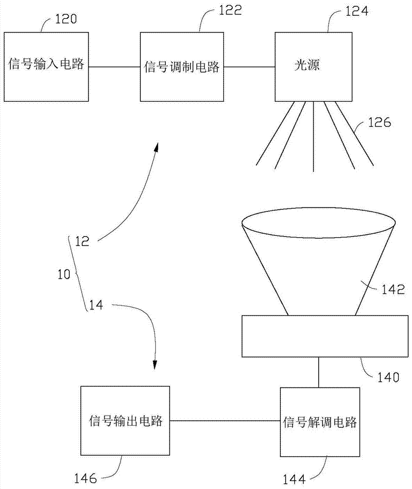
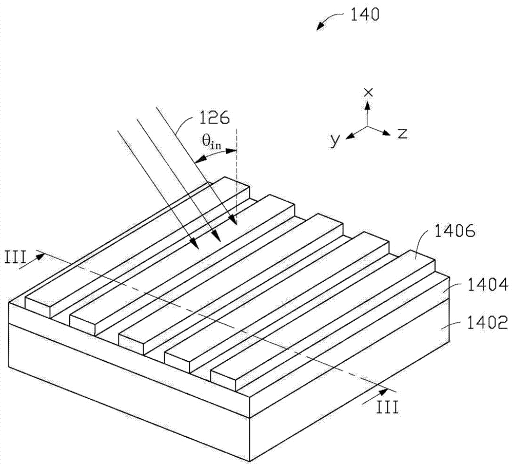
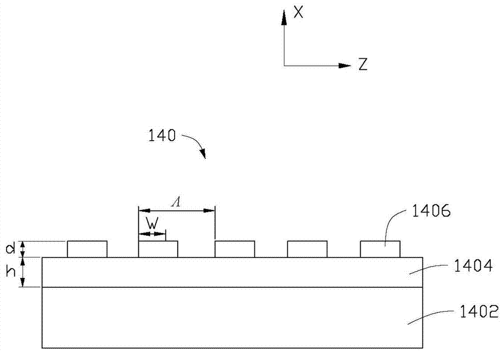
[0068] The light source 124 includes an RGB three-color combination white LED array and an LED driver module electrically connected to the LED array. The signal modulation circuit 122 includes a DFT-S-OFDM modulator. The substrate 1402 is a silicon dioxide layer with a thickness of 0.5 mm. The waveguide layer 1404 is a titanium dioxide layer with a thickness of h=255 nm, and covers the entire surface of the substrate 1402 . The metal grating 1406 includes multiple figure 2 As shown in the rectangular aluminum metal strip, the width w of the rectangular aluminum metal strip is 170 nanometers, the period Λ is 340 nanometers, the thickness d is 50 nanometers, and the duty ratio f=w / Λ is 0.5. The medium on the surface of the filter 140 is air. See Figure 6 , is a scanning electron micrograph of the filter prepared in Example 1. It can be understood that aluminum has the smallest skin depth in the visible light band and the smallest equivalent refractive index in the visible...

Embodiment 2

[0071] This embodiment is basically the same as Embodiment 1, except that the light source 124 includes an RGBA four-color combination white LED array and an LED driver module electrically connected to the LED array. The signal modulation circuit 122 includes a DFT-S-OFDM modulator. The substrate 1402 is a silicon dioxide layer with a thickness of 0.5 mm. The waveguide layer 1404 is a titanium dioxide layer with a thickness of h=420 nm, and covers the entire surface of the substrate 1402 . The metal grating 1406 includes multiple figure 2 As shown in the rectangular aluminum metal strip, the width w of the rectangular aluminum metal strip is 155 nanometers, the period Λ is 310 nanometers, the thickness d is 70 nanometers, and the duty ratio f=w / Λ is 0.5. See Figure 9 , is a scanning electron micrograph of the filter prepared in Example 2.

[0072] Further, in this embodiment, the four-bandpass filtering performance of the optical filter 140 is simulated and tested experi...

Embodiment 3

[0074] This embodiment is basically the same as Embodiment 1, the difference being that the metal grating 1406 is made of gold. From Figure 12 It can be seen that the optical filter designed in this embodiment basically meets the three-pass band filtering requirements.


PUM


Abstract

A visible light communication system of the present invention comprises a light signal emission device and a light signal reception device supporting the use of the light signal emission device and comprising a light filter, wherein the light filter is characterized by comprising a substrate; a waveguide layer arranged on the surface of the substrate, wherein the refractive index of the waveguide layer is greater than the refractive index of the substrate; and a metal grating arranged on the surface of the waveguide layer and comprising a plurality of metal strips arranged at equal intervals, and wherein the parameters of the light filter satisfy the following formulas (1)-(3), so that the light filter can realize the multi-bandpass light filtering. The light filter of the visible light communication system can realize the multi-bandpass light filtering, so that the visible light communication system possesses a higher signal utilization rate.

Description

technical field [0001] The present invention relates to the field of visible light communication, in particular to a visible light communication system. Background technique [0002] Visible Light Communication technology (Visible Light Communication, VLC) refers to the use of light in the visible light band as an information carrier, without using optical fiber and other wired channel transmission media, and directly transmits optical signals in the air. LED Visible light communication uses the characteristics of visible light-emitting diodes (Light Emitting Diode, LED) to switch faster than fluorescent lamps and incandescent lamps. The information is modulated and transmitted by the high-speed modulated light wave signal, and then the optical carrier signal is received by photodiode and other photoelectric conversion devices to obtain the information. [0003] Regardless of whether it is applied to indoor or outdoor visible light LED communication systems, its physical re...

Claims


Application Information

Patent Timeline
Patent Type & Authority Patents(China)
IPC IPC(8): H04B10/67H04B10/116G02B5/20
CPCG02B5/20H04B10/116H04B10/675
Inventor 谭峭峰王绮霞顾华荣
Owner TSINGHUA UNIV
Why Eureka
Try Eureka