A generation circuit and a control method of a digital oscilloscope reference clock

A digital oscilloscope and reference clock technology, which is applied in the field of testing technology, can solve the problems of not being able to meet the requirements at the same time, increasing the difficulty of debugging, and not being able to meet the requirements of providing a 10MHz reference clock to the outside world at the same time, so as to improve practicability and convenience, save hardware costs and Wiring space and the effect of improving signal utilization

Inactive Publication Date: 2019-04-23
CHINA ELECTRONIS TECH INSTR CO LTD
View PDF5 Cites 0 Cited by
  • Summary
  • Abstract
  • Description
  • Claims
  • Application Information

AI Technical Summary

Problems solved by technology

One is to generate a reference clock through a hardware circuit on the function board and send it to other function boards through a connector to meet the internal requirements of the oscilloscope for a 10MHz reference clock, but it cannot simultaneously provide a stable and accurate 10MHz reference clock to the outside; the other is Place reference clock generation circuits on different functional boards inside the oscilloscope. Although the reference clock requirements of each functional board can be realized, when different functional boards interact, additional circuits need to be designed to match the reference clock, which increases the difficulty of debugging.
However, neither of the above two methods can satisfy the observation of an externally input 10MHz reference clock in the same hardware circuit at the same time.
[0004] That is to say, although the existing technical solutions can realize the generation and transmission of the 10MHz reference clock, they cannot simply and efficiently realize the input of the external 10MHz reference clock, the output of the internal 10MHz reference clock, and the clock input to different functional boards inside the oscilloscope. and other functions

Method used


Image

  • A generation circuit and a control method of a digital oscilloscope reference clock
  • A generation circuit and a control method of a digital oscilloscope reference clock
  • A generation circuit and a control method of a digital oscilloscope reference clock

Examples


Embodiment 1

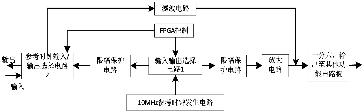
[0036] Such as figure 1 As shown, a digital oscilloscope reference clock generation circuit includes a 10MHz reference clock generation circuit, an input and output selection control circuit, and interconnection circuits between various functional circuit boards inside the oscilloscope and the generation circuit. The input and output selection control circuit includes FPGA control and input and output selection circuit 1, reference clock input / output selection circuit 2, controls the FPGA to output different control bits through the human-computer interaction interface, controls the switch on and off, and realizes the 10MHz reference clock in one channel External output, reference clock input to each function board inside the oscilloscope, and external reference clock input.

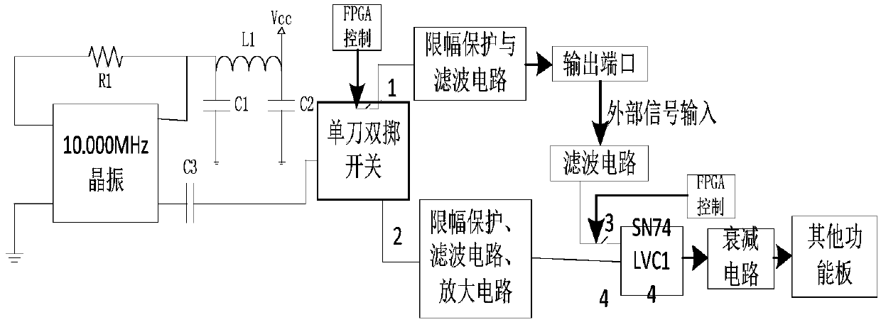
[0037] The 10MHz reference clock generation circuit includes a 10MHz crystal oscillator, capacitors C1, C2, DC blocking capacitor C3, resistor R1, and inductor L1; input and output selection circuit 1 an...

Embodiment 2

[0044] The control method of the generation circuit of the digital oscilloscope reference clock described in Embodiment 1 mainly includes the following steps:

[0045] 10MHz reference clock generation steps;

[0046] Steps of input and output selection control;

[0047] Steps for external reference clock input;

[0048] Steps for internal reference clock output;

[0049] The steps of outputting the reference clock to each functional circuit board inside the oscilloscope.

[0050] In the step of generating the 10MHz reference clock, a stable 10MHz reference clock is obtained through the 10MHz crystal oscillator, Vcc provides power to the 10MHz crystal oscillator through the inductor L1, capacitors C1, and C2, and the DC blocking capacitor C3 realizes the external clock output of the 10MHz crystal oscillator ; In the step of input and output selection control, the FPGA realizes the external output of the 10MHz reference clock and the reference of each function board inside th...


PUM


Abstract

The invention discloses a generation circuit and a control method of a reference clock of a digital oscilloscope. The generating circuit comprises a 10MHz reference clock generating circuit, an input / output selection control circuit and a parallel circuit of the functional circuit boards in the oscilloscope and the generating circuit. The input and output selection control circuit comprises an FPGA control and input and output selection circuit 1 and a reference clock input / output selection circuit 2, the FPGA is controlled to output different control bits through a human-computer interactioninterface; the external output of a 10MHz reference clock, the reference clock input of each function board in the oscilloscope and the input of an external reference clock are realized in one channel. In the whole process, a user only needs to select a 10MHz reference clock as a reference input or a reference output on a human-computer interaction interface, so that the practicability and the convenience of the oscilloscope are improved, and the functions of the oscilloscope are enriched.

Description

technical field [0001] The invention belongs to the technical field of testing, and in particular relates to a generation circuit and a control method of a reference clock of a digital oscilloscope, which is applied to an internal 10MHz reference clock of a digital oscilloscope, and can complete the input of an external reference clock and output it as a reference clock externally and to each of the internal oscilloscopes. The reference clock input of the function board realizes the input and output of the 10MHz reference clock on one channel. Background technique [0002] 10MHz is a commonly used frequency band in the test field, and a reference clock of this frequency is required in the internal circuit of the oscilloscope and other test circuits to achieve signal time base matching. The stability and accuracy of the reference clock will have a great impact on the test results, resulting in wrong test results. Moreover, when testing the 10MHz internal function board of th...

Claims


Application Information

Patent Timeline
Patent Type & Authority Applications(China)
IPC IPC(8): G06F1/04G01R13/02
CPCG01R13/0254G06F1/04
Inventor 王啸刘洪庆向前李云彬
Owner CHINA ELECTRONIS TECH INSTR CO LTD
Why Eureka
Try Eureka