Concentric Array Optical System

An optical system and array technology, applied in the field of optical systems, can solve the problems of large field of view optical systems that cannot meet actual needs, etc., and achieve the effects of compact size, simplified system form, and improved capabilities

Active Publication Date: 2022-06-21
CHANGCHUN UNIV OF SCI & TECH
View PDF1 Cites 0 Cited by
  • Summary
  • Abstract
  • Description
  • Claims
  • Application Information

AI Technical Summary

Problems solved by technology

[0003] In order to solve the problem that the size of the existing large field of view optical system cannot meet the actual needs, the present invention provides a concentric array optical system

Method used


Image

  • Concentric Array Optical System
  • Concentric Array Optical System
  • Concentric Array Optical System

Examples


Embodiment Construction

[0025] The present invention will be described in further detail below with reference to the accompanying drawings and embodiments.

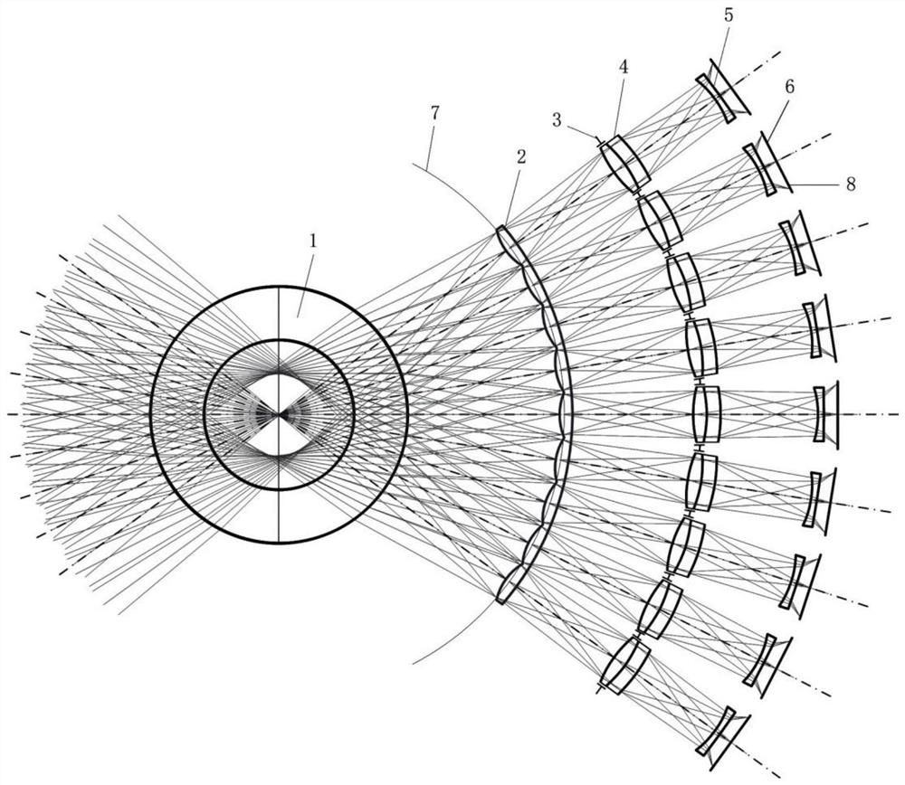
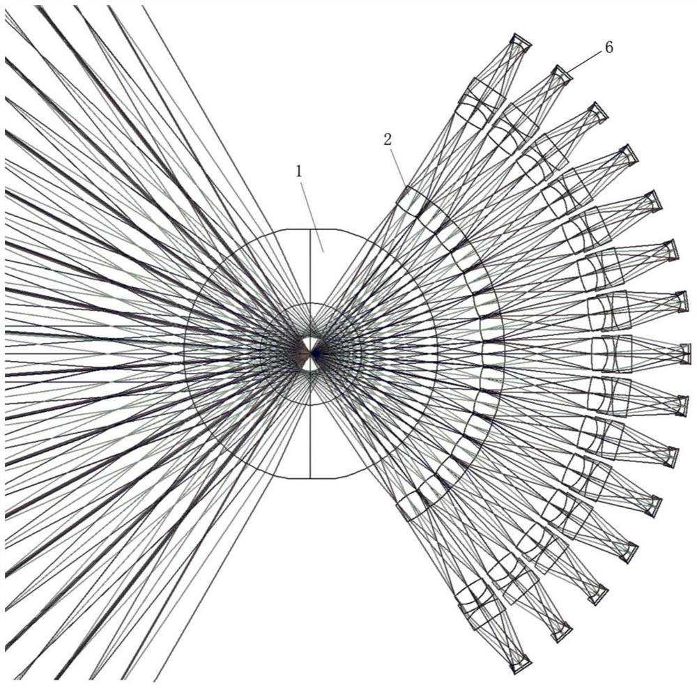
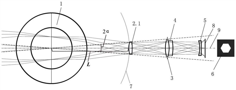
[0026] The concentric array optical system includes a concentric lens 1, an array lens 2 and a subsystem, and the subsystem includes an aperture stop 3, a lens group and a field stop 6, such as figure 1 shown. The array lens 2 includes N sub-lenses 2.1, the number of subsystems is N, and N is an integer greater than or equal to 2. The subsystems are arranged in a one-to-one correspondence with the sub-lenses 2.1. In the concentric array optical system, the target beam is imaged once through the concentric lens 1, and is imaged twice through the array lens 2 and the subsystem. The array lens 2 is arranged on the image plane of one imaging.

[0027] beam transmission process, such as figure 1 , figure 2 and image 3 : The target beam is converged by the concentric lens 1 and then irradiated onto the sub-lens 2.1. The light beam irradiated o...


PUM


Abstract

The concentric array optical system relates to the technical field of optical systems, and solves the problem that the size of the existing system does not meet the requirements, including: a concentric lens, through which a target beam passes through the concentric lens to achieve primary imaging; an array lens, the array lens is arranged on a primary image plane , including N sub-lens units; the target beam is irradiated on the sub-lens unit after being converged by a concentric lens, and the sub-lens unit deflects the beam irradiated on it to the direction corresponding to the optical axis of the sub-system; the sub-system, one sub-system corresponds to one sub-lens unit The lens unit is arranged, and the subsystem includes an aperture stop and a lens group; the light beam deflected by the sub-lens unit is first limited by the aperture stop and then secondarily imaged by the lens group. The invention can obtain a wide range of field of view, simplify the structure of the concentric system, ensure a small three-dimensional space size of the system, ensure the response strength of the detector and reduce the difficulty of image processing.

Description

technical field [0001] The present invention relates to the technical field of optical systems, in particular to a concentric array optical system. Background technique [0002] The large field of view optical system can obtain large field of view information, which is helpful to realize a wide range of detection, and has a very wide range of applications in the fields of detection and security. In the existing large field of view optical systems, the ratio of the axial size of the system to the system entrance pupil aperture, and the ratio of the radial size to the system entrance pupil aperture are generally several tens of times, which is difficult to meet the practical application requirements for the size of the large field of view optical system. need. SUMMARY OF THE INVENTION [0003] In order to solve the problem that the size of the existing large-field optical system cannot meet the actual demand, the present invention provides a concentric array optical system....

Claims


Application Information

Patent Timeline
Patent Type & Authority Patents(China)
IPC IPC(8): G02B13/06G02B27/00
CPCG02B13/06G02B27/0012
Inventor 刘智颖黄蕴涵
Owner CHANGCHUN UNIV OF SCI & TECH
Why Eureka
Try Eureka