Air gap fixed type synchronous permanent magnet coupler

A fixed, coupling technology, applied in the direction of permanent magnet clutch/brake, electric brake/clutch, electrical components, etc., can solve the application performance and stability of synchronous permanent magnet coupling, safety impact, easy collision , permanent magnet suction, etc., to improve stability and safety, ensure efficient production, and reduce vibration and noise.

Pending Publication Date: 2020-05-05
CCTEG SHENYANG RES INST
View PDF0 Cites 0 Cited by
  • Summary
  • Abstract
  • Description
  • Claims
  • Application Information

AI Technical Summary

Problems solved by technology

However, the existing synchronous permanent magnet coupler input assembly and output assembly have no positioning, and the air gap (that is, the gap between the two corresponding permanent magnets in the input assembly and output assembly) is not fixed. Axial and radial movement is prone to occur, resulting in collisions between permanent magnets and related components, resulting in equipment damage or even scrapping
[0004] Since the inner and outer rotors of the existing synchronous permanent magnet coupling are relatively independent, without connection and support, and the suction force between the permanent magnets is relatively large, it is difficult to align during installation and disassembly, the air gap is variable and not fixed, and collisions are prone to occur. It is time-consuming and labor-intensive to use other components (such as taper sleeve structure, etc.) to assist the centering or manually centering on site; the inner and outer rotors need to be shipped separately during transportation, and are easy to cause damage during the process. If they are to be shipped together as a whole, they need to be connected by auxiliary parts During operation, the air gap between the inner and outer rotors is small. If there is an installation deviation or the fixing bolts of the motor and other equipment are loose and shifted, it is very easy to collide with the permanent magnets and related components in the two rotors, resulting in irreversible equipment damage.
This causes the existing synchronous permanent magnet coupling to be greatly affected in terms of application performance, stability, and safety.

Method used


Image

  • Air gap fixed type synchronous permanent magnet coupler
  • Air gap fixed type synchronous permanent magnet coupler
  • Air gap fixed type synchronous permanent magnet coupler

Examples


Embodiment 1

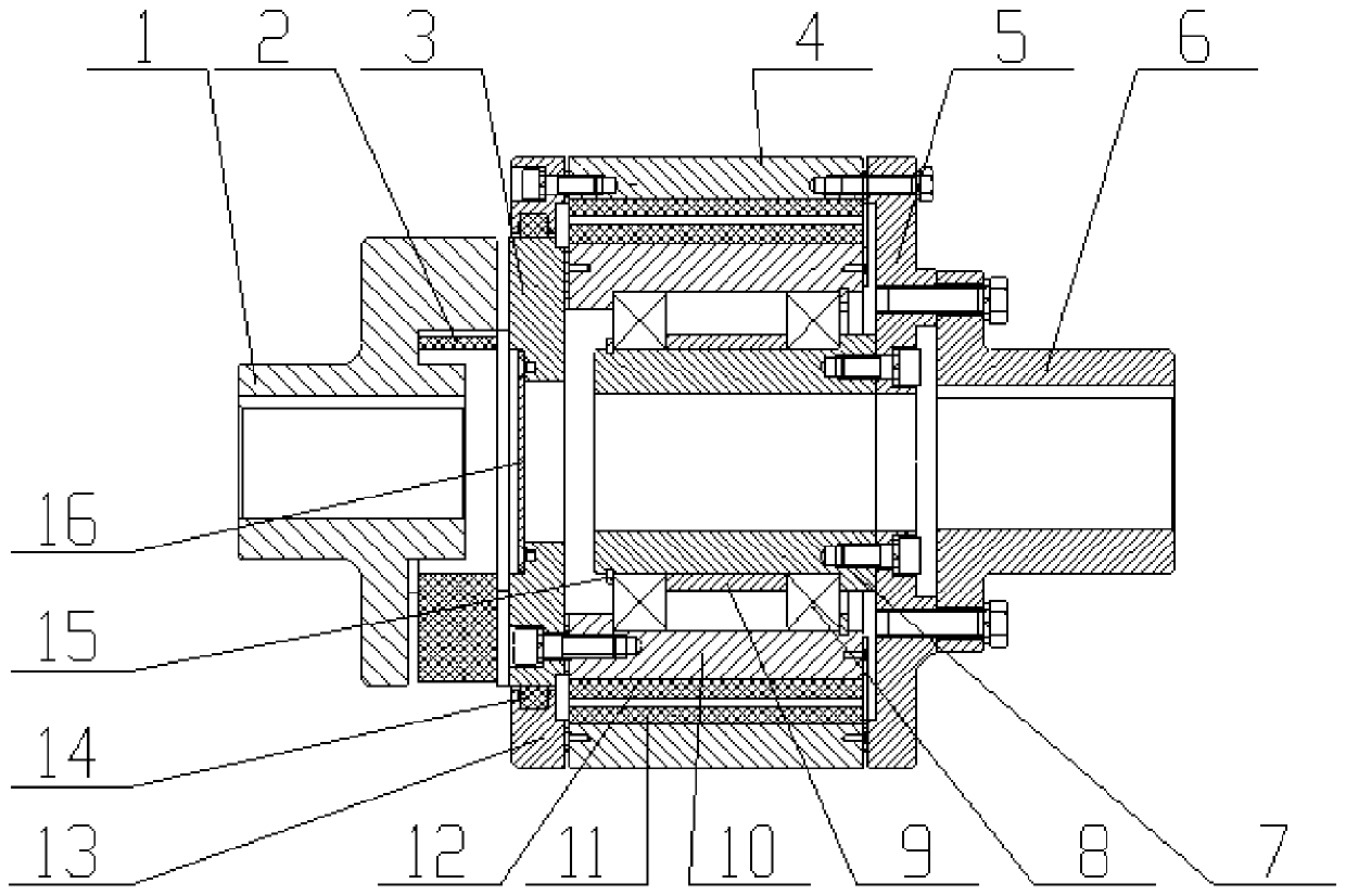
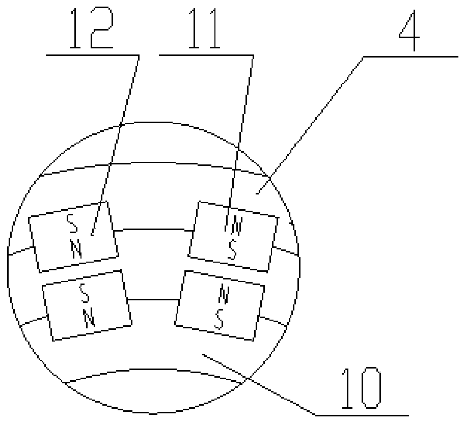
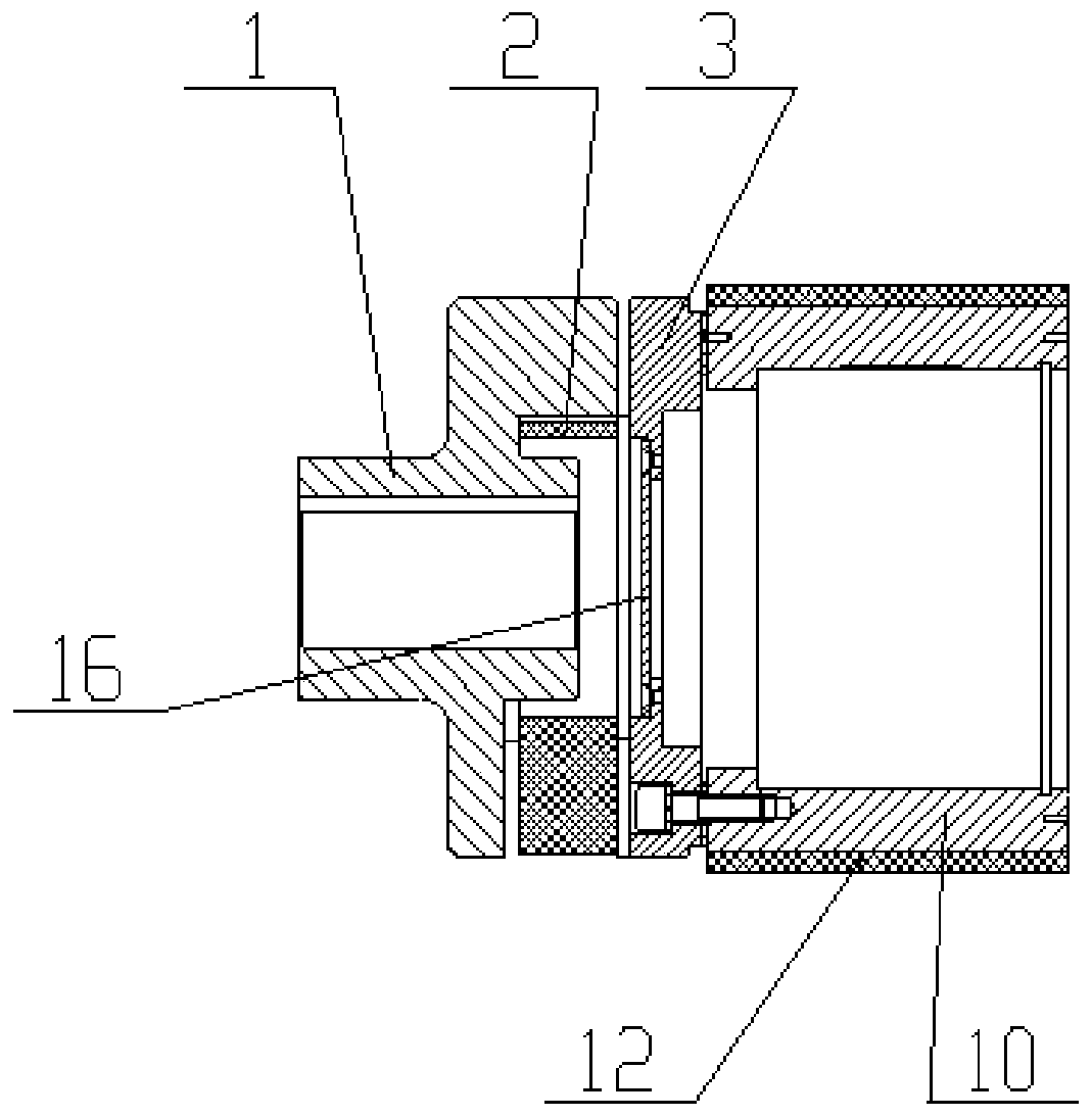
[0032] Such as Figure 1-Figure 4 As shown, the air gap fixed synchronous permanent magnet coupling proposed in this embodiment includes an input connection plate 3; an inner rotor 10, which is connected to the end face of the input connection plate 3 near the output end; an output connection plate 5; an outer rotor 4, Connected to the end surface of the output connection plate 5 close to the input end, the inner rotor 10 is installed inside the outer rotor 4, the inner rotor 10 and the outer rotor 4 are coaxially arranged, and the outer ring surface of the inner rotor 10 and the inner ring surface of the outer rotor 4 form a Air gap; output end connector, the output end connector is fixedly connected to the output connection plate 5, the output end connector extends to the inside of the inner rotor 10, and the outer ring surface of the output end connector located in the inner section of the inner rotor 10 is circular and connected to the The inner rotor 10 is arranged concen...

Embodiment 2

[0045] Such as Figure 5 As shown, the fixed-air-gap synchronous permanent-magnet coupling in this embodiment is similar to the fixed-air-gap synchronous permanent-magnetic coupling in Embodiment 1, the difference lies in the structure of the connector at the output end.

[0046] The output end connector is an output shaft 71 , which is fixedly connected to the output connecting disk 5 , and part of the shaft section of the output shaft 71 extends to the inside of the inner rotor 10 . In the case of keeping other components unchanged, the original output shaft 71 can be modified by canceling the output coupling 6, and the shaft hole can be processed to match the diameter and length of the shaft end of the reducer, and the corresponding connection can be added. keyway, so as to directly insert the reducer shaft into the restructured output shaft 71, which can adapt to the working environment with a small axial length and meet the requirements of different on-site working condit...


PUM


Abstract

The invention belongs to the technical field of permanent magnet transmission, and relates to an air gap fixed type synchronous permanent magnet coupler which comprises an inner rotor. The inner rotoris connected with the end face, close to the input end, of an input connecting disc. The coupler comprises an outer rotor which is connected with the end face, close to the input end, of an output connecting disc. The inner rotor is installed in the outer rotor. The inner rotor and the outer rotor are coaxially arranged, and an air gap is formed between the outer ring face of the inner rotor andthe inner ring face of the outer rotor. The coupler comprises an output end connecting piece which is fixedly connected with the output connecting disc. The output end connecting piece extends into the inner rotor, and the outer ring surface of the section, located in the inner rotor, of the output end connecting piece is circular and is coaxial with the inner rotor. The coupler comprises a bearing assembly which is installed between the outer ring surface of the output end connecting piece and the inner ring surface of the inner rotor, and the bearing assembly is used for rotatably positioning and supporting the output end connecting piece and the inner rotor. The permanent magnet coupler can realize relative fixation of positions, namely air gaps, between the inner rotor and the outer rotor, and avoids the problem of collision caused by displacement during operation.

Description

technical field [0001] The invention belongs to the technical field of permanent magnet transmission, in particular to a fixed air gap synchronous permanent magnet coupling. Background technique [0002] In the machinery industry, transmission equipment is generally connected to power equipment such as motors and then connected to equipment such as reducers to transmit torque. At present, the transmission equipment in my country is mainly shaft couplings, hydraulic couplings, and asynchronous permanent magnetic couplings. The structure of the coupling is simple, but there are problems such as difficulty in alignment, easy wear, and large vibration and noise. Although the latter two types of transmission equipment have solved some problems of the coupling, they all need to rely on the existence of slip to realize energy transfer during operation. Transmission, there is a large loss of efficiency, and it is easy to cause the temperature of the transmission parts to rise. When...

Claims


Application Information

Patent Timeline
Patent Type & Authority Applications(China)
IPC IPC(8): H02K49/10H02K7/00
CPCH02K7/003H02K49/106
Inventor 王雷李健王鹏张黎李松刘昊周海江刘丽丽
Owner CCTEG SHENYANG RES INST
Why Eureka
Try Eureka