Combined type centrifugal ore separator directly driven by permanent magnetic synchronous motor
A technology of permanent magnet synchronous motor and centrifugal concentrator, which is applied in the direction of centrifuges, electrical components, electromechanical devices, etc., which can solve the problem of affecting the processing capacity and production efficiency per unit area, hydraulic motors and motors cannot be driven at the same time, and the failure rate is high. Affect the speed of mineral processing and other issues to achieve the effect of maximizing the utilization of resources, simplifying the driving mode and structure, and improving resource utilization
- Summary
- Abstract
- Description
- Claims
- Application Information
AI Technical Summary
Problems solved by technology
Method used
Image
Examples
Embodiment 1
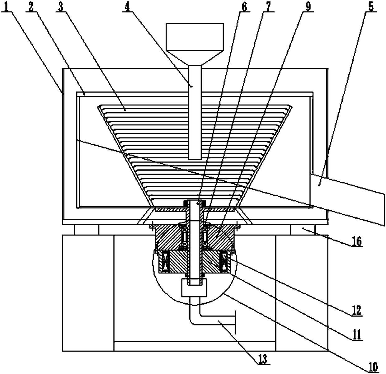
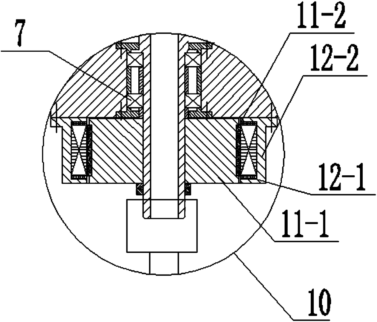
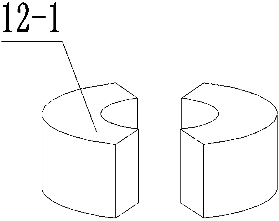
[0035] Such as Figure 1-3 As shown, the stator assembly 12 also includes a stator base 12-2; the stator core 12-1 is fixedly installed on the stator base 12-2, and the stator base 12-2 is installed on the on the support block 9; the mover 11-1 is in the form of an annular column; the permanent magnets 11-2 are evenly distributed on the outer wall of the mover 11-1; the stator base 12-2 is in the form of an annular column structure and is sleeved outside the rotor assembly 11; the stator core 12-1 is placed on the inner side wall of the stator base 12-2, and the stator core 12-1 is symmetrical along the circumference relative to the axis Two sector blocks arranged in the same direction are formed, and the stator core is set opposite to the permanent magnet 11-2. A plurality of through holes are uniformly distributed on the wall surface of the stator base 12-2, and a waterproof and breathable membrane (not shown in the figure) is provided on the through holes.
[0036] After ...
Embodiment 2
[0038] Such as Figure 4-5 As shown, the stator assembly 12 also includes a stator base 12-2; the stator core 12-1 is fixedly installed on the stator base 12-2, and the stator base 12-2 is installed on the on the support block 9; the mover 11-1 is in the form of an annular disc; the permanent magnets 11-2 are evenly distributed on the top surface of the mover 11-1; the stator base 12-2 is in the form of an annular disc structure and is sheathed above the rotor assembly 11; the stator core 12-1 is placed on the bottom surface of the stator base 12-2, opposite to the permanent magnet 11-2. A rotating fan blade 14 is arranged on the rotating shaft 6 below the permanent magnet synchronous motor, and a protective cover 15 with a through hole is arranged outside the rotating fan blade 14 . Wherein, there are 6 stator cores 12-1, and the 6 stator cores with fan-shaped block structure are spliced end to end to form a full annular disk structure when installed.
[0039] After elect...
Embodiment 3
[0041] Such as Figure 6 As shown, the stator assembly 12 also includes a stator base 12-2; the stator core 12-1 is fixedly installed on the stator base 12-2, and the stator base 12-2 is installed on the on the support block 9; the mover 11-1 is in the form of an annular column, sleeved on the rotating shaft 6; the permanent magnets 11-2 are evenly distributed on the outer wall and top of the mover 11-1 surface; the stator base 12-2 has an annular cap structure and is sleeved outside the rotor assembly 11; the stator core 12-1 is placed on the inner side wall and bottom surface of the stator base 12-2, and The permanent magnets 11-2 are arranged oppositely. The stator core 12-1 is a sector block structure (not specifically shown in the figure) uniformly arranged along the circumferential direction around the axis.
[0042] After electrification, the mover 11-1 provides a radial and axial rotating magnetic field for the stator core 12-1, prompting the stator assembly 12 and t...
PUM
 Abstract
Description
Claims
Application Information
 - R&D
- Intellectual Property
- Life Sciences
- Materials
- Tech Scout
- Unparalleled Data Quality
- Higher Quality Content
- 60% Fewer Hallucinations
Browse by: Latest US Patents, China's latest patents, Technical Efficacy Thesaurus, Application Domain, Technology Topic, Popular Technical Reports.
© 2025 PatSnap. All rights reserved.Legal|Privacy policy|Modern Slavery Act Transparency Statement|Sitemap|About US| Contact US: help@patsnap.com


