Self-locking mechanism for lifting machine

A lift and self-locking technology, which is applied in the direction of lifting frames and lifting devices, can solve problems such as easy slipping of the equipment to be lifted, weak bottom support, and inability to lift, so as to ensure the working stability of the mechanism and increase the Manual operation function, avoiding the effect of sudden drop

Pending Publication Date: 2020-05-08
JIAXING VOCATIONAL TECHN COLLEGE
View PDF0 Cites 1 Cited by
  • Summary
  • Abstract
  • Description
  • Claims
  • Application Information

AI Technical Summary

Problems solved by technology

[0006] In order to solve the above-mentioned technical problems, the present invention provides a self-locking mechanism for a lift to solve the problem that the existing self-locking mechanism has poor self-locking effect, cannot fix the equipment to be lifted and easily slips, and the bottom support is not firm and has no electricity. The problem of not being able to lift in the case of

Method used


Image

  • Self-locking mechanism for lifting machine
  • Self-locking mechanism for lifting machine
  • Self-locking mechanism for lifting machine

Examples


Embodiment Construction

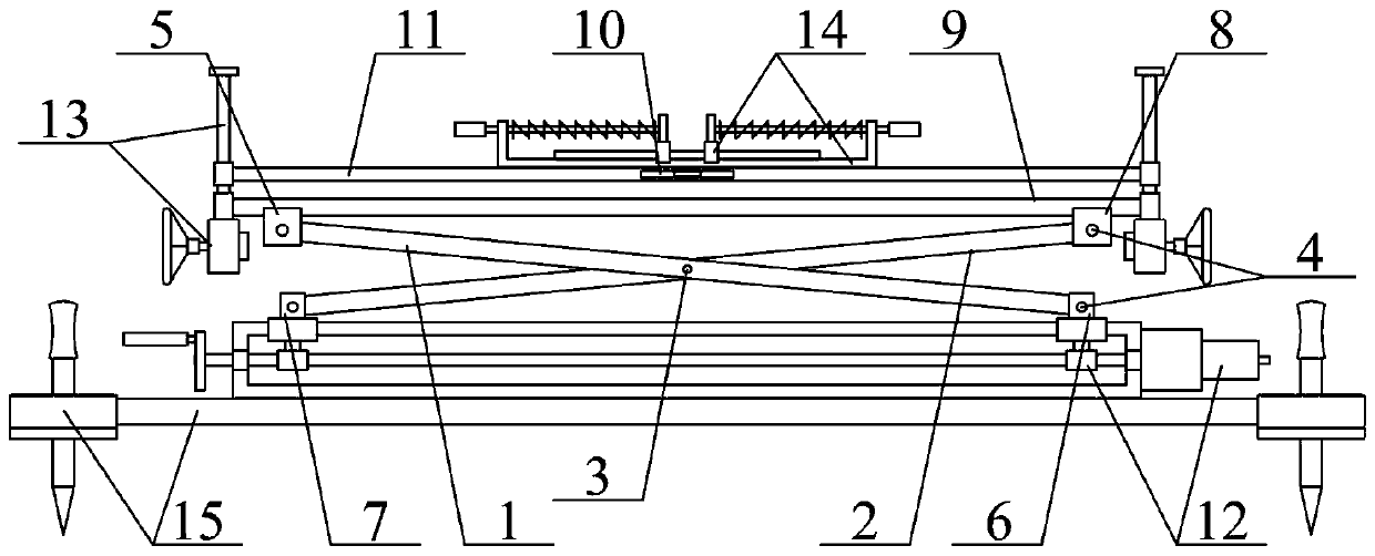
[0038] The present invention is described in detail below in conjunction with accompanying drawing, as appended figure 1 And attached figure 2 As shown, the self-locking mechanism for the lift includes the active flat head rod 1, the driven movable flat head rod 2, the movable shaft 3, the connecting shaft 4, the first U-shaped slider 5, and the first mounting seat 6 , the second mounting seat 7, the second U-shaped slider 8, the lifting linear slide rail 9, the horizontal bead 10, the lifting platform 11, the self-locking non-slip lifting rod structure 12, the manual non-electrically operated lifting rod structure 13, which can Adjust the anti-slip lifting clamp structure 14 and the anti-sag bottom support fixed frame structure 15, the joint between the active flat head rod 1 and the driven movable flat head rod 2 is set through the movable shaft 3; the described One end of the active flat head rod 1 is connected to the inner lower end of the first U-shaped slider 5 through...


PUM


Abstract

The invention provides a self-locking mechanism for a lifting machine. The self-locking mechanism comprises a driving movable flat-head rod, a driven movable flat-head rod, a movable shaft, a connecting shaft, a first U-shaped sliding block, a first installation seat, a second installation seat, a second U-shaped sliding block, a lifting linear sliding rail, a horizontal bead, a lifting table, a self-locking type anti-skid lifting rod structure, a manual electroless operation lifting rod structure, an adjustable anti-skid lifting clamping seat structure and an anti-falling bottom supporting fixed frame structure, and joints between the driving movable flat-head rod and the driven movable flat-head rod are movably connected through the movable shaft. By arranging a check ring, a lifting screw, a lifting nut, an installation lining seat, an electroless gear reducer and a hand wheel, manual lifting operation is conveniently carried out without electricity; and the hand wheel is held in hand for rotation, so that the electroless gear reducer drives the lifting screw to rotate in the installation lining seat, and the lifting nut drives the lifting table to perform a lifting action on the outer wall of the lifting screw, so that the mechanism working stability is ensured.

Description

technical field [0001] The invention belongs to the technical field of self-locking mechanisms, in particular to a self-locking mechanism for a lift. Background technique [0002] Car lift refers to the car maintenance equipment used for car lifting in the car maintenance industry. Lifts play a vital role in vehicle maintenance and maintenance. No matter whether the vehicle is overhauled or minor repairs, it is inseparable from it. The nature and quality of its products directly affect the personal safety of maintenance personnel. In the repair and maintenance enterprises of different sizes, whether it is a comprehensive repair shop that repairs multiple models, or a street shop with a single business scope (such as a tire shop), almost all of them are equipped with lifts. [0003] At present, there are various lifts, but all of them are inseparable from the support of the self-locking mechanism. [0004] However, the existing self-locking mechanism also has the problems o...

Claims


Application Information

Patent Timeline
Patent Type & Authority Applications(China)
IPC IPC(8): B66F7/06B66F7/28
CPCB66F7/0608B66F7/065B66F7/28
Inventor 孔祥金宋忆雯
Owner JIAXING VOCATIONAL TECHN COLLEGE
Why Eureka
Try Eureka