Road and bridge fence protective guard structure

A technology for guardrails and bridges, applied to roads, bridges, roads, etc., can solve the problems of destroying family happiness, threats to people on board, casualties, etc., and achieve the effect of light and novel structure, novel connection structure and improved safety

Pending Publication Date: 2020-05-08
SHANDONG XINGHUA CONSTR GRP
View PDF0 Cites 2 Cited by
  • Summary
  • Abstract
  • Description
  • Claims
  • Application Information

AI Technical Summary

Problems solved by technology

[0002] With the gradual improvement of people's living standards, more and more families have cars. However, the incidence of car accidents is also increasing year by year. The light ones consume money, and the serious ones cause casualties, which destroys family happiness. Among them, on highways or bridges The fatality rate of traffic accidents in this location is the highest. If a car suddenly blows out while driving at high speed, the car will deviate from the route and crash into the guardrail.
The safety guardrails of existing road bridges are mostly made of steel or cement, and the structural design is simple, only in the shape of columns connected with cross bars. In addition, the traditional guardrails are mainly rigid structures. Without buffer force, the car will be subjected to a very strong reaction force, which will easily cause a huge threat to the occupants of the car

Method used


Image

  • Road and bridge fence protective guard structure
  • Road and bridge fence protective guard structure
  • Road and bridge fence protective guard structure

Examples


Embodiment 1

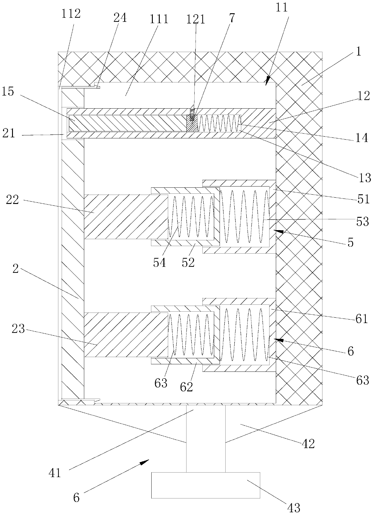
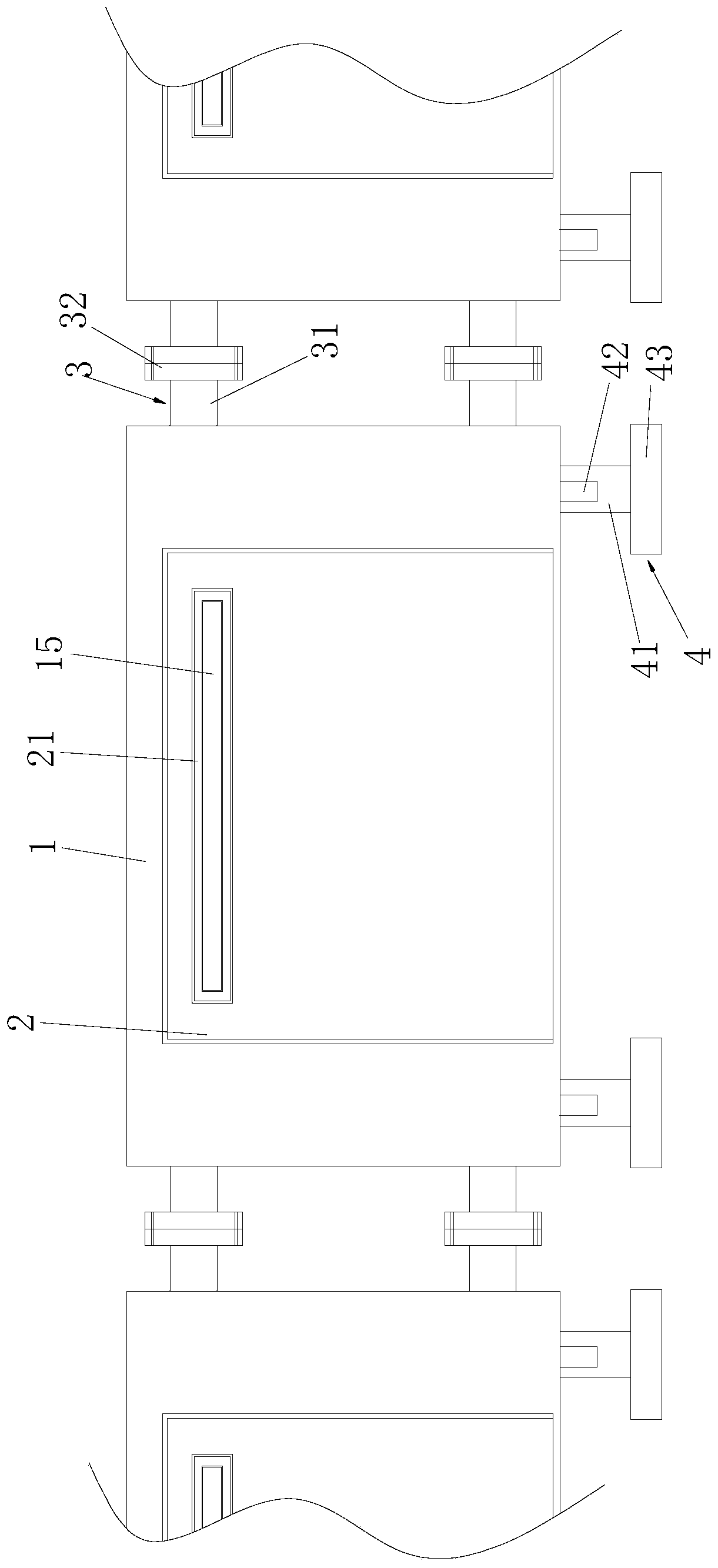
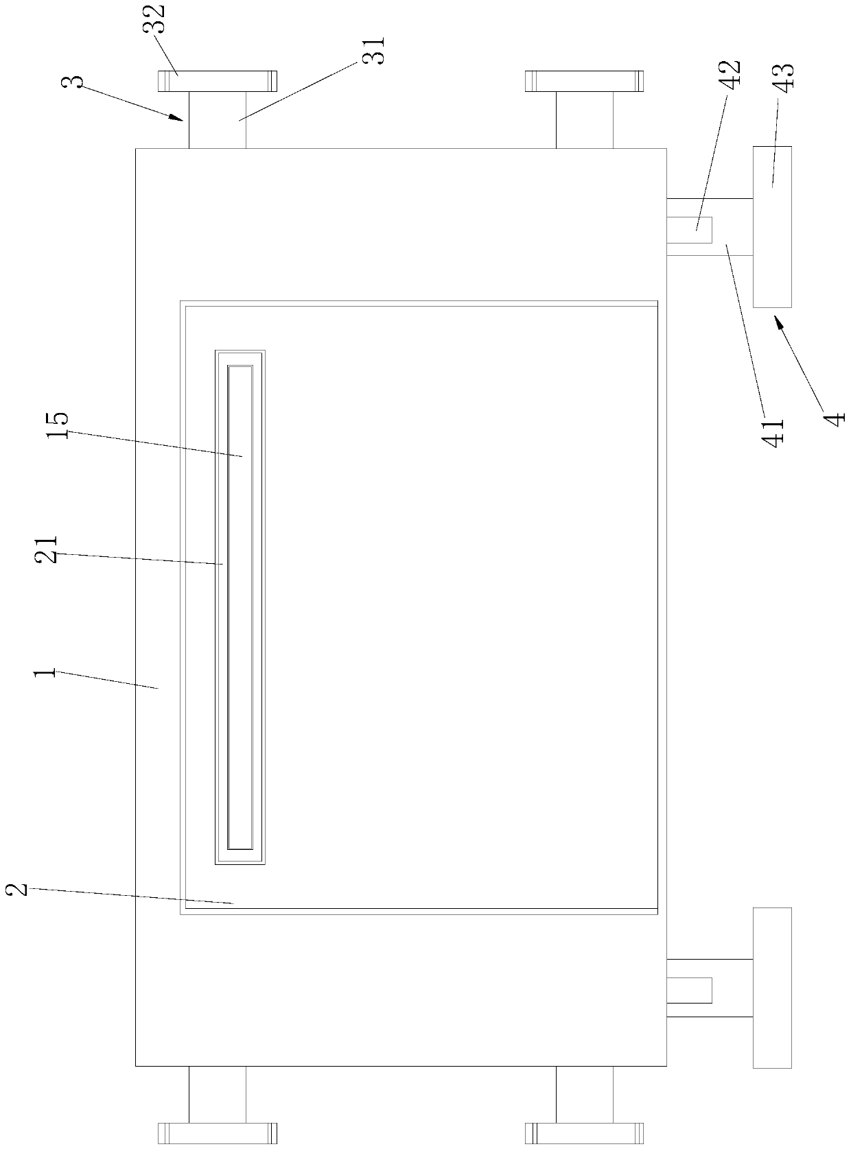
[0037] combine Figure 1 to Figure 4 , a road and bridge fence structure, including a plurality of buffer protection devices, the buffer protection device includes a main protection support 1 and a buffer main board 2, the front and rear ends of the main protection support 1 are fixedly connected with a plate connection assembly 3, the protection The lower end of the main support 1 is connected with a support frame 4 .

[0038] One side of the protective main support 1 is provided with a first support groove 11, and a first lifting horizontal plate 12 is arranged in the upper part of the first support groove 11, and the middle and lower parts of the first support groove 11 A first buffer mechanism 5 and a second buffer mechanism 6 are respectively provided. The upper part of the buffer main board 2 is provided with a first main board slot 21 , and the inner side of the middle part and the lower part of the buffer main board 2 are connected with a first moving post 22 and a se...

Embodiment 2

[0055] The above-mentioned road and bridge fence structure is provided with a new type of buffer protection device. The device is provided with a new type of protective main support 1 and a buffer main board 2, and between the main protective support 1 and the buffer main board 2 is firstly provided with a second The first buffer mechanism 5 and the second buffer mechanism 6 of the primary buffer. When the first buffer mechanism 5 and the second buffer mechanism 6 fail or the buffer effect weakens, the buffer sub-plate 15 pops up for secondary buffering.

[0056] When the car hits the guardrail, it will first crash into the buffer main board 2, and the second buffer spring and the fourth buffer spring compress to alleviate the impact on the buffer main board 2. When the impulse is too large, the first buffer spring and the third buffer spring are compressed to further reduce the impulse received by the buffer main board 2. Through the setting of the first buffer spring, the se...

Embodiment 3

[0058] When the impulse of the car to the buffer main board 2 exceeds the limit buffer capacity of the first buffer spring, the second buffer spring, the third buffer spring and the fourth buffer spring, when the buffer main board 2 moves to the position of the first upper extension block 721, The first upper protruding block 721 is inserted into the first lifting slot 121 .

[0059] Then the first upper protruding piece 721 squeezes the first lower protruding piece 731 into the inside of the first connecting rod longitudinal groove 711, and then the first internal compression spring 14 returns to its original length, and the first internal compression spring 14 compresses the first The limit connecting rod 71 and the buffer sub-plate 15 are pushed outward, and after the buffer sub-plate 15 contacts the hit vehicle and receives the force from the upper right side of the vehicle, part of the buffer sub-plate 15 is stuck in the groove of the second lifting plate 13, and there is...


PUM


Abstract

The invention discloses a road and bridge fence protective guard structure. The structure comprises a plurality of buffer protective devices, and each buffer protective device comprises a protective main supporting seat and a buffer main plate. A first supporting seat groove is formed in one side of the protective main supporting seat, and a first lifting transverse plate, a first buffer mechanismand a second buffer mechanism are arranged in each first supporting seat groove; a first main plate slotted hole is formed in the upper part of each buffer main plate; a first moving column and a second moving column are connected into the middle part and the lower part of each buffer main plate; the first lifting transverse plates are clamped in the first main plate slotted holes, the first moving columns are connected with the first buffer mechanisms, and the second moving columns are connected with the second buffer mechanisms; second lifting plate grooves are formed in the first lifting transverse plates, first inner compression springs and buffering auxiliary plates are arranged in the second lifting plate grooves, and the buffering auxiliary plates are connected with the first lifting transverse plates through first limiting mechanisms. The road and bridge fence protective guard structure can perform multi-stage buffering, and is higher in safety, simpler and more novel in structure and high in innovativeness.

Description

technical field [0001] The invention relates to the field of engineering machinery, in particular to a road and bridge fence structure. Background technique [0002] With the gradual improvement of people's living standards, more and more families have cars. However, the incidence of car accidents is also increasing year by year. The light ones consume money, and the serious ones cause casualties, which destroys family happiness. Among them, on highways or bridges The fatality rate of traffic accidents in this location is the highest. If a car suddenly blows out while driving at high speed, the car will deviate from the route and crash into the guardrail. The safety guardrails of existing road bridges are mostly made of steel or cement, and the structural design is simple, only in the shape of columns connected with cross bars. In addition, the traditional guardrails are mainly rigid structures. Without the buffer force, the car will be subjected to a very strong reaction f...

Claims


Application Information

Patent Timeline
Patent Type & Authority Applications(China)
IPC IPC(8): E01D19/10E01F15/02E01F15/14
CPCE01D19/10E01D19/103E01F15/02E01F15/145
Inventor 孙刚薛宝川路绪刚国娟解群
Owner SHANDONG XINGHUA CONSTR GRP
Why Eureka
Try Eureka