Detachable handle connecting structure of pot

A connection structure and detachable technology, applied in the field of detachable handle connection structure of cookware, can solve the problems of increased danger, poor connection structure between the handle and the body, and no temperature prompt function, etc., so as to improve the use safety, The effect of reducing scalding accidents and novel connection structure

Pending Publication Date: 2020-11-03
淮安钛谷科技有限公司
View PDF0 Cites 0 Cited by
  • Summary
  • Abstract
  • Description
  • Claims
  • Application Information

AI Technical Summary

Problems solved by technology

During the cooking process, the heat generated by the pot body will be directly transferred to the pot handle, thereby increasing the temperature of the pot handle. Even if a rubber or plastic cover is set on the pot handle, it still cannot achieve good heat insulation and anti-scalding effect
It may even occur that the handle of the pot cannot be held by hand and cause burns to the user.
[0003] Disadvantages of the prior art: 1. The heat insulation effect of the pot handle is poor, and it cannot be heated for a long time, and it is easy to burn the user; 2. The traditional pot handle (rubber cover or plastic cover) has poor appearance and is not beautiful; 3. The pot is Daily cooking tools have high usage rate and are indispensable. There is no temperature prompt function, which increases the danger of use; 4. The shape of the pot body is a traditional hemispherical shape, which has no aesthetics at all; 5. The distance between the handle and the pot body Poor connection structure, short service life and low reliability

Method used


Image

  • Detachable handle connecting structure of pot
  • Detachable handle connecting structure of pot
  • Detachable handle connecting structure of pot

Examples


Embodiment Construction

[0023] The present invention will be further described in detail below in conjunction with the accompanying drawings, so that those skilled in the art can implement it with reference to the description.

[0024] It should be understood that terms such as "having", "comprising" and "including" as used herein do not entail the presence or addition of one or more other elements or combinations thereof.

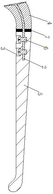
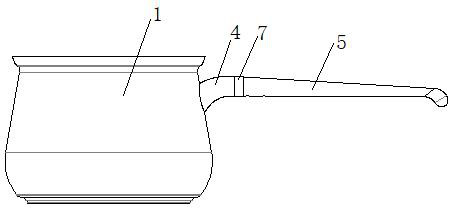
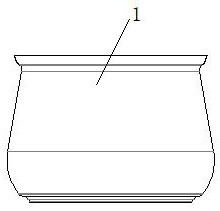
[0025] Figures 1 to 6 It shows an implementation form according to the present invention, which includes: a pot body 1, one end of the core rod 2 is fixedly connected to the side of the pot body 1, and the front part of the core rod 2 close to the pot body 1 is bent and the rear part is flat. Straight, the material of the core rod 2 is titanium metal, a fixing hole 3 is set on the straight rear section of the core rod 2, and an elbow 4 and a handle 5 are sequentially sleeved on the core rod 2, and the material of the elbow is ceramics, the handle is made of carbon fiber, the ha...


PUM


Abstract

The invention discloses a detachable handle connecting structure of a pot, and the structure comprises a pot body, wherein one end of a core rod is fixedly connected to the side face of the pot body,the front section, close to the pot body, of the core rod is bent, the rear section, close to the pot body, of the core rod is straight, a fixing hole is formed in the straight rear section of the core rod, and the core rod is sequentially connected with an elbow and a handle in a sleeved mode. The handle is provided with a hole corresponding to the fixing hole in the core rod, the elbow is connected to the bent position of the core rod in a matched and sleeved mode, the handle is connected to the straight position of the core rod in a matched and sleeved mode, the handle is installed on the core rod through a screw in the fixing hole, and the core rod between the elbow and the handle is connected with the temperature measuring ring in a sleeved mode. The connecting structure of the pot handle and the pot body is novel, convenient to install, high in reliability and long in service life; the temperature measuring ring is heated to expand to extrude the elbows and the handles on the twosides, no gap exists at the contact positions of all components on the core rod, the fixing effect is good, no moving phenomenon is generated, and positioning is stable.

Description

technical field [0001] The invention relates to a pot. More specifically, the present invention relates to a detachable handle connection structure for pots. Background technique [0002] Pots have become an indispensable kitchen utensil in daily cooking at home. The traditional way of connecting the pot handle and the pot body is to fasten the pot body and the pot handle through bolts. The pot handle is made of metal and is directly attached to the pot. physically. During the cooking process, the heat generated by the pot body will be directly transferred to the handle of the pot, thereby increasing the temperature of the handle of the pot. Even if a rubber cover or a plastic cover is set on the handle of the pot, it still cannot achieve a good heat insulation and anti-scalding effect. It may even occur that the pot handle cannot be held by hand and causes the user to be scalded. [0003] Disadvantages of the prior art: 1. The heat insulation effect of the pot handle i...

Claims


Application Information

Patent Timeline
IPC IPC(8): A47J45/07A47J45/08
CPCA47J45/071A47J45/08
Inventor 赵名越古建国王天翔张正夏松
Owner 淮安钛谷科技有限公司
Why Eureka
Try Eureka