Cloth roll wrapping positioning device and cloth inspecting roll wrapping machine

A positioning device and wrapping technology, applied in the directions of transportation and packaging, winding strips, and thin material processing, can solve the problems that the cloth cannot be formed into a cylinder, the cloth cannot be accurately rolled, and the labor force is increased, and the connection structure is achieved. Simple and novel, simple and novel structure, good curl positioning effect

Pending Publication Date: 2020-06-05
青岛同利佳机械科技有限公司
View PDF0 Cites 1 Cited by
  • Summary
  • Abstract
  • Description
  • Claims
  • Application Information

AI Technical Summary

Problems solved by technology

In the process of wrapping the cloth, it is necessary to use a wrapping mechanism to wrap the cloth into a circular cloth tube. During the cloth rolling process, the cloth rolling roller rotates to gradually wrap the cloth into a cylindrical shape. During the process, the cloth wrapped on the cloth roller gradually thickens, and the subsequent cloth may be offset when the cloth is rotated, so that the cloth wrapped on the cloth roller cannot be formed into a cylindrical shape.
[0003] And because the cloth is pulled tighter and tighter during the cloth rolling process, the cloth rolling roller may rotate on its own during the later cloth rolling process without driving the cloth roll formed by the cloth to rotate, resulting in that the rear cloth cannot be rolled onto the cloth roll accurately , the phenomenon of decoiling occurs
This requires workers to constantly correct the wrapping position of the cloth, which not only increases the labor force, but also reduces the efficiency, and because the cloth roll is rotating, it may also cause certain safety hazards

Method used


Image

  • Cloth roll wrapping positioning device and cloth inspecting roll wrapping machine
  • Cloth roll wrapping positioning device and cloth inspecting roll wrapping machine
  • Cloth roll wrapping positioning device and cloth inspecting roll wrapping machine

Examples


Embodiment 1

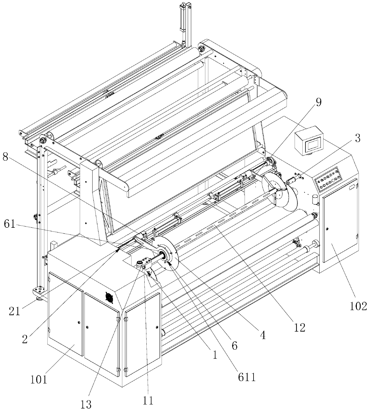
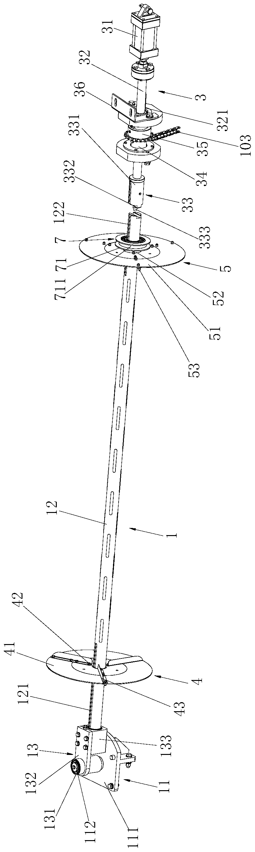
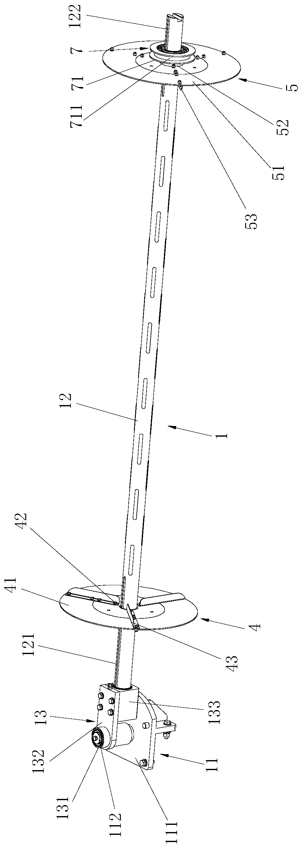
[0053] combine Figure 1 to Figure 5 , a cloth wrapping positioning device, including a cloth rolling mechanism 1, a toggle mechanism 2 and a transmission mechanism 3, the cloth rolling mechanism includes an air expansion shaft fixing seat 11 and an air expansion shaft rod 12, and the air expansion shaft fixing seat 11 passes through the rotating arm assembly 13 is connected with one end of the air expansion shaft 12, the first cloth roll clamping assembly 4 and the second cloth roll clamping assembly 5 are positioned on the air expansion shaft 12, and the outer end of the first cloth roll clamping assembly 4 is connected to There is a first toggle adapter assembly 6, and a second toggle adapter assembly 7 is connected to the outer end of the second cloth clamping assembly 5.

[0054] The toggle mechanism 2 comprises a swing shaft 21, a first cylinder 22, a first main toggle assembly 8 and a second main toggle assembly 9, one end of the swing shaft 21 is connected with a first...

Embodiment 2

[0088] combine Figure 1 to Figure 5 , a cloth inspection and wrapping machine, including a left casing 101 and a right casing 102, and also includes the above-mentioned cloth wrapping positioning device, which is connected between the left casing 101 and the right casing 102. When the cloth wrapping positioning device is connected, the air shaft fixing seat 11 is fixed on the left casing 101 by bolts.

[0089] The transmission mechanism 3 includes a second cylinder 31 and a transmission shaft 32 connected to the second cylinder 31. The transmission shaft 32 is connected to the other end of the air expansion shaft 12 through a telescopic shaft joint 33. The transmission shaft 32 is covered with a transmission shaft. The axle sleeve 34 is fixedly connected with the transmission sprocket 35 outside the transmission axle sleeve 34.

[0090]The second cylinder 31 in the transmission mechanism 3 is arranged in the right casing 102, and the inner wall of the right casing 102 is pro...

Embodiment 3

[0092] combine Figure 1 to Figure 5 , when the above-mentioned cloth inspection and wrapping machine is working normally, the cloth is transferred to the cloth wrapping positioning device through the transmission system in the cloth inspection and wrapping machine to complete the wrapping of the cloth. When wrapping the cloth, the first main toggle assembly 8 in the toggle mechanism 2 drives the first fabric clamping assembly 4 to slide leftward on the inflatable shaft 12 through the first toggle adapter assembly 6 , the second main toggle assembly 9 drives the second roll cloth clamping assembly 5 to slide on the telescopic shaft joint 33 through the second toggle adapter assembly 7 .

[0093] Then the first air cylinder 22 works to drive the swing shaft 21 to rotate upwards. During the rotation of the swing shaft 21, it drives the first main toggle assembly 8 and the second main toggle assembly 9 to rotate. The first main toggle assembly 8 and the first The toggle adapter ...


PUM


Abstract

The invention discloses a cloth roll wrapping positioning device and a cloth inspecting roll wrapping machine. The cloth roll wrapping positioning device comprises a cloth rolling mechanism, a pushingmechanism and a transmission mechanism; the cloth rolling mechanism comprises an air expansion shaft fixing base and an air expansion shaft rod connected to the air expansion shaft fixing base, and afirst cloth rolling clamping assembly and a second cloth rolling clamping assembly are positioned and connected to the air expansion shaft rod; the pushing mechanism comprises a swinging shaft rod, afirst air cylinder, a first main pushing assembly and a second main pushing assembly, the first air cylinder is connected with one end of a first swinging arm, and the first main pushing assembly isconnected with the first cloth rolling clamping assembly through a first pushing adapter assembly; and the transmission mechanism comprises a second air cylinder and a transmission shaft rod connectedto the second air cylinder, the transmission shaft rod is connected with the other end of the air expansion shaft rod through a telescopic shaft joint, and the second main pushing assembly is connected with the second cloth rolling clamping assembly through a second pushing adapter assembly. According to the positioning device, cloth can be stably and efficiently rolled, and the cloth inspectingroll wrapping machine can more efficiently and more safely conduct cloth inspecting roll wrapping on the cloth.

Description

technical field [0001] The invention relates to the field of textile machinery, in particular to a cloth wrapping positioning device and a cloth inspection wrapping machine. Background technique [0002] The cloth inspection machine is a set of necessary special equipment for inspecting large-format, double-width and single-width cloth such as cotton, wool, linen, silk and chemical fiber before production in the garment industry. The cloth inspection machine automatically completes the work of length recording and package arrangement. The working method of the cloth inspection machine: provide the hardware environment for cloth inspection, continuously unfold the fabric in sections, provide sufficient light source, the operator can find surface defects and color differences by visual observation, and the cloth inspection machine will automatically complete the work of length recording and package finishing. In the process of wrapping the cloth, it is necessary to use a wrap...

Claims


Application Information

Patent Timeline
Patent Type & Authority Applications(China)
IPC IPC(8): B65H18/02B65H75/28B65H18/10B65H19/30
CPCB65H18/028B65H18/10B65H19/30B65H75/285
Inventor 张耀亮
Owner 青岛同利佳机械科技有限公司
Why Eureka
Try Eureka