Eureka AIR delivers breakthrough ideas for toughest innovation challenges, trusted by R&D personnel around the world.

Joint calibration method based on laser radar and camera and computer readable storage medium

A lidar and joint calibration technology, applied in the field of calibration, can solve the problems of depth discontinuity, inaccurate calibration edge points, affecting the accuracy of calibration results, etc., to avoid the problem of insufficient accuracy and achieve the effect of accurate calibration results

Active Publication Date: 2020-05-08
海南智博睿科技有限公司
View PDF4 Cites 9 Cited by
  • Summary
  • Abstract
  • Description
  • Claims
  • Application Information

AI Technical Summary

Problems solved by technology

At present, most of the joint calibration methods between multi-line lidar and camera use some calibration objects with spatial geometric characteristics, and use the depth discontinuity of lidar points at the edge to extract points with sudden distance changes as edge points for calibration. The feature points are registered with the edge information extracted from the image, but due to the influence of the resolution of the lidar, the point of the distance mutation is not exactly at the edge of the object, so the obtained calibration edge point is not accurate, which affects the calibration accuracy of results

Method used


Image

  • Joint calibration method based on laser radar and camera and computer readable storage medium
  • Joint calibration method based on laser radar and camera and computer readable storage medium
  • Joint calibration method based on laser radar and camera and computer readable storage medium

Examples


Embodiment Construction

[0022] In order to make the purposes, technical solutions and advantages of the embodiments of the present application clearer, the technical solutions in the embodiments of the present application will be clearly and completely described below in conjunction with the drawings in the embodiments of the present application. Obviously, the described embodiments It is a part of the embodiments of this application, but not all of them. Based on the embodiments in the present application, all other embodiments obtained by persons of ordinary skill in the art without making creative efforts belong to the protection scope of the present application.

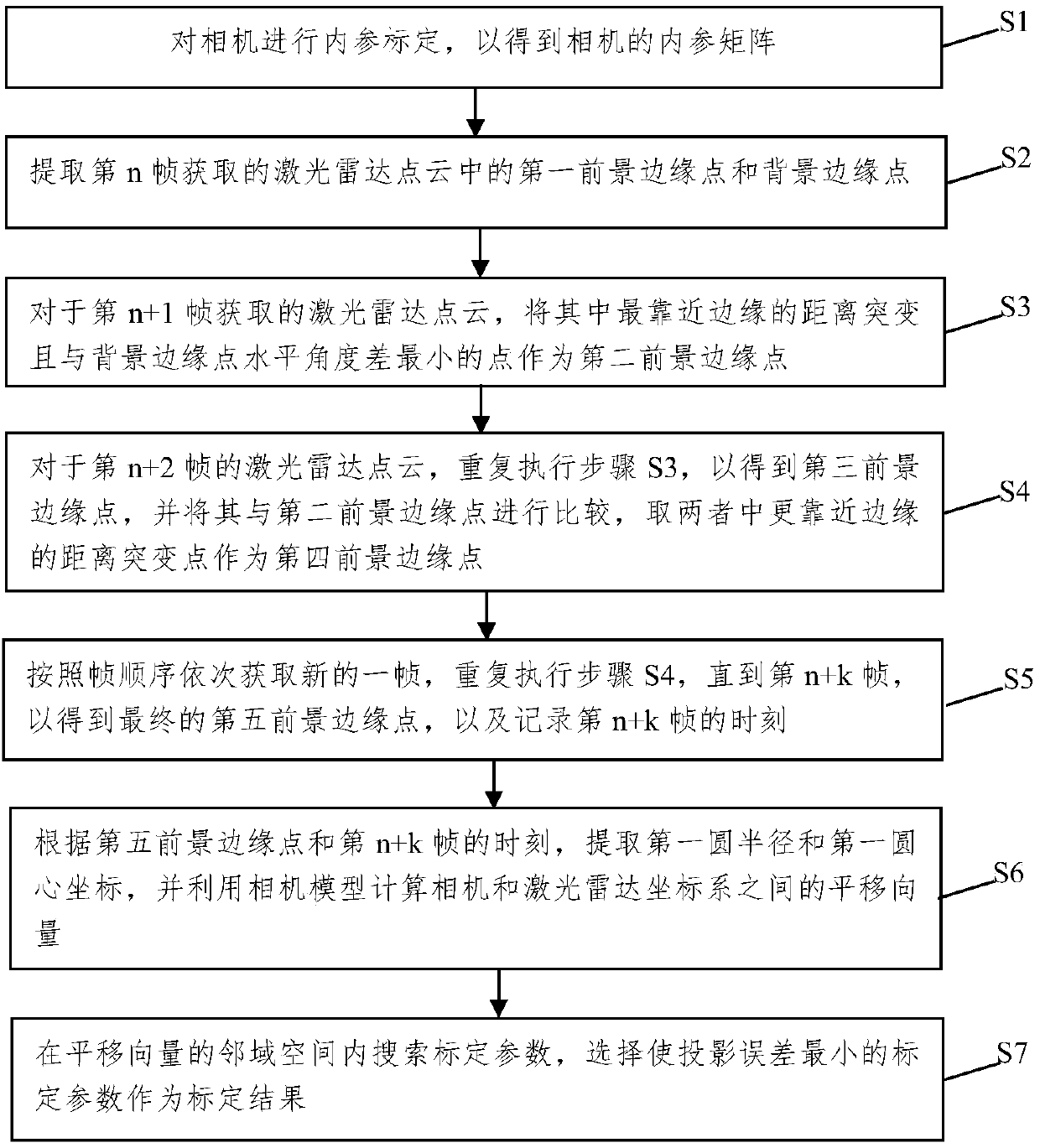
[0023] The embodiment of this application provides a joint calibration method based on lidar and camera, such as figure 1 As shown, the joint calibration method may include the following steps:

[0024] Step S1, perform internal reference calibration on the camera to obtain the internal reference matrix of the camera.

[0025] In this...


PUM


Abstract

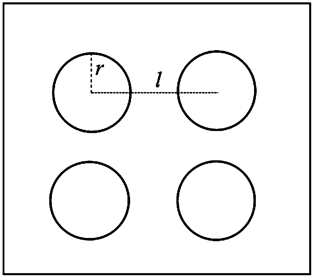
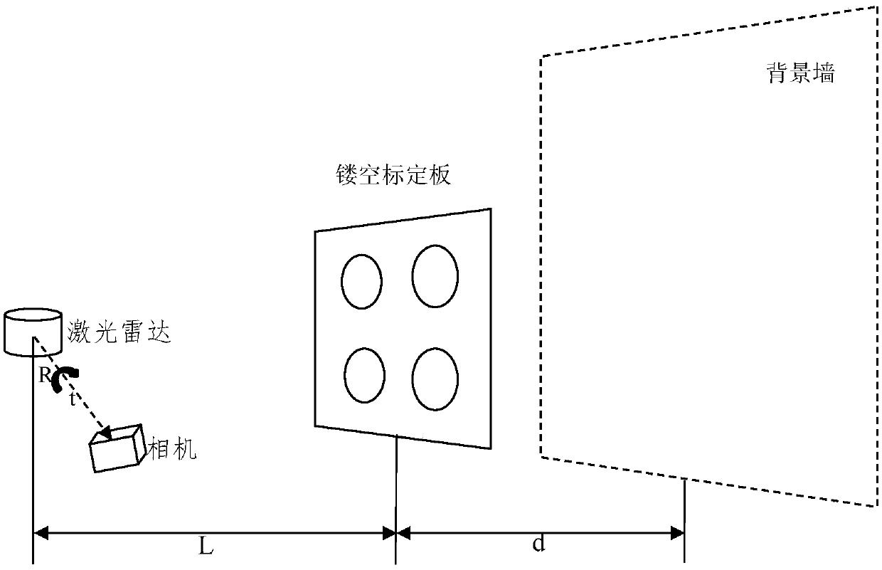
The invention relates to a joint calibration method based on a laser radar and a camera and a computer readable storage medium. The joint calibration method comprises the following steps of: carryingout edge detection on a laser radar point cloud extracted by the laser radar, extracting edge points of a background part, searching a foreground edge point corresponding to each background edge pointthrough a depth difference of laser radar points; performing repeated searching and comparison to obtain foreground edge points closer to an edge, then respectively extracting the laser radar edge point cloud and the circle center and radius of a circle in an edge image acquired by the camera at a same moment, calculating a translation vector between the camera and the laser radar through a pinhole camera model, searching calibration parameters in a neighborhood space of the obtained translation vector so as to find a calibration result minimizing the projection error. Points scanned by the laser radar at the edge of an object can be extracted with high precision, and the problem of insufficient precision caused by low resolution of the laser radar can be avoided. Through the obtained precise edge points, a more accurate calibration result can be obtained.

Description

technical field [0001] The present application relates to the field of calibration, and in particular to a joint calibration method based on laser radar and camera and a computer-readable storage medium. Background technique [0002] The fusion of lidar and camera is widely used in 3D reconstruction in robot vision, autonomous navigation and positioning, and drones. A single sensor has limitations, such as cameras are susceptible to light and blurred external environments, and lidar data points are sparse, and the fusion of the two can make up for their respective shortcomings. [0003] In order to fuse the information acquired by lidar and camera, joint calibration between the two is essential. The mutual conversion relationship between the two sensor space coordinate systems is determined through calibration, so that the information obtained by different sensors can be fused into a unified coordinate system. At present, most of the joint calibration methods between multi...

Claims


Application Information

Patent Timeline
Patent Type & Authority Applications(China)
IPC IPC(8): G01S7/497G06T7/80
CPCG01S7/497G06T7/80
Inventor 张剑华巴瑛
Owner 海南智博睿科技有限公司
Why Eureka
Eureka Blog
Learn More