Three-phase conductor commutation connector

A technology of three-phase conductors and phase conductors, which is applied in the direction of connection, clamping/spring connection, and parts of connection devices, etc., which can solve the problems of inability to achieve phase sequence interchange

Active Publication Date: 2020-05-08
PINGGAO GRP +2
View PDF9 Cites 5 Cited by
  • Summary
  • Abstract
  • Description
  • Claims
  • Application Information

AI Technical Summary

Problems solved by technology

[0003] The purpose of the present invention is to provide a three-phase conductor commutation joint to solve the problem in the prior art that the gas-insulated metal-enclosed switchgear with three phases arranged in a line cannot realize phase sequence interchange

Method used


Image

  • Three-phase conductor commutation connector
  • Three-phase conductor commutation connector
  • Three-phase conductor commutation connector

Examples


Embodiment Construction

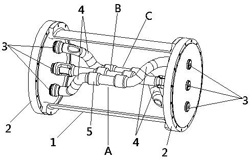
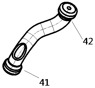
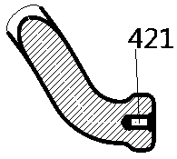
[0022] In order to make the object, technical solution and advantages of the present invention clearer, the present invention will be further described in detail below in conjunction with the accompanying drawings and embodiments. It should be understood that the specific embodiments described here are only used to explain the present invention, and are not intended to limit the present invention, that is, the described embodiments are only some of the embodiments of the present invention, but not all of the embodiments. The components of the embodiments of the invention generally described and illustrated in the figures herein may be arranged and designed in a variety of different configurations.

[0023] Accordingly, the following detailed description of the embodiments of the invention provided in the accompanying drawings is not intended to limit the scope of the claimed invention, but merely represents selected embodiments of the invention. Based on the embodiments of the...


PUM


Abstract

The invention relates to a three-phase conductor phase-change connector which comprises a sealing cylinder and sealing flanges installed at two ends of the sealing cylinder, the two sealing flanges are each provided with three through connection inserts, and the through connection inserts on the two sealing flanges are arranged in the same straight line in the extending direction. A three-phase conductor is arranged in the sealing cylinder, and two ends of the three-phase conductor are correspondingly connected with the three switching inserts on the two sealing flanges respectively; and two-phase conductors at two sides in the three-phase conductors are provided with bending sections, so that two ends of each phase of conductor in the two-phase conductors are respectively connected with the two switching inserts which are arranged on the two sealing flanges and are positioned at two sides of the axis of the sealing cylinder body. By means of the arrangement, under the condition that the three-phase arrangement modes of the two ends of the three-phase conductor commutation connector are the same, the phase sequence interchange of a phase A and a phase C can be achieved, in the actual use process, the three-phase conductor commutation connector is directly installed at a three-phase connector of equipment, the phase sequence interchange of the phase A and the phase C is achieved, and therefore, the connection of three-phase different-phase-sequence equipment is achieved.

Description

technical field [0001] The invention relates to a three-phase conductor phase change joint. Background technique [0002] Most of the gas-insulated metal-enclosed switchgears on the market today are designed in a three-phase common box. The three-phase conductors are arranged in a triangular shape and in-line. , the advantages of high common rate of three-phase components are gradually accepted by the market. However, when the three-phase in-line structure is actually used, it is sometimes necessary to exchange the phase sequence of the A and C phases in which the three-phases are in-line (for example, although two sets of equipment that need to be connected together use three-phase It is arranged in a horizontal line, but the positions of A and C phases are different), and there is currently no good way to achieve phase sequence interchange. Contents of the invention [0003] The purpose of the present invention is to provide a three-phase conductor commutation joint to...

Claims


Application Information

Patent Timeline
IPC IPC(8): H01R31/02H01R4/36H01R13/502H01R13/627H01R13/629H01R13/642
CPCH01R31/02H01R13/502H01R13/627H01R13/629H01R4/36H01R13/642H02B13/035
Inventor 贺永明谭盛武段晓辉魏建巍王刚白玮刘龙魏义涛井琼琼李旭旭李晓斌李俊锋张超军占小猛孙清超
Owner PINGGAO GRP
Why Eureka
Try Eureka