
A screed arrangement

A technology of screed and soleplate, applied in the direction of road, construction, road repair, etc., to achieve the effect of cost-effective and simple design

Active Publication Date: 2020-05-08
VOLVO CONSTR EQUIP
View PDF9 Cites 0 Cited by
  • Summary
  • Abstract
  • Description
  • Claims
  • Application Information

AI Technical Summary

Problems solved by technology

[0005] A problem with the screed arrangement described above is that the oscillating tamper bar arrangement is positioned in the gap between the deflector member and the soleplate

Method used


Image

  • A screed arrangement
  • A screed arrangement
  • A screed arrangement

Examples


Embodiment Construction

[0034] The present invention will now be described more fully hereinafter with reference to the accompanying drawings, in which exemplary embodiments of the invention are shown. However, this invention may be embodied in many different forms and should not be construed as limited to the embodiments set forth herein; rather, these embodiments are provided for sufficiency and completeness. Throughout the specification, the same reference numerals denote the same elements.

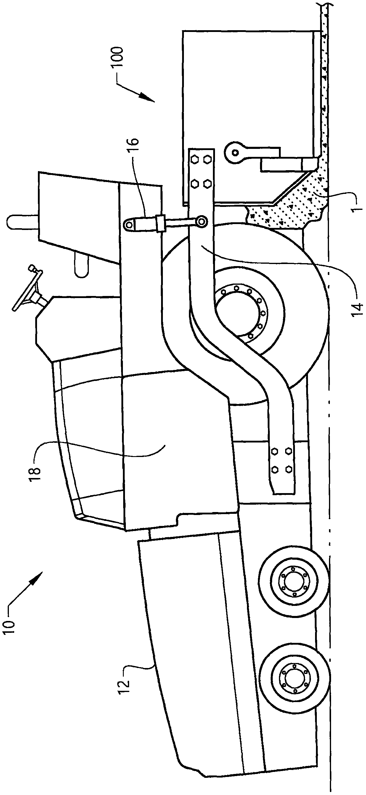
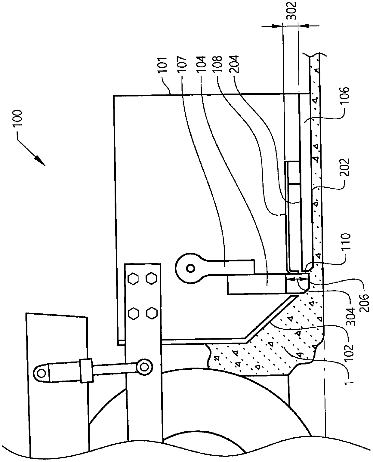
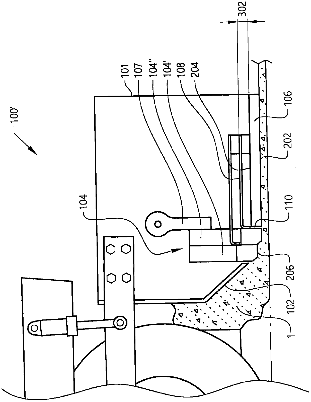
[0035] special reference figure 1 According to the invention, a vehicle 1 in the form of a paver is provided. The paver 1 is arranged to dispense paving material 1 , which is hereinafter referred to as asphalt, although it is also conceivable to dispense other types of material. The paver 10 includes a hopper 12 into which asphalt material is supplied, for example, from a dump truck. The paver 10 also includes a screed arrangement 100 at its rear end. The screed assembly 100 is connected to the paver 10 b...


PUM


Abstract

The present invention relates to a screed arrangement (100, 100') for a paver machine. The screed arrangement (100) comprises a screed body (101) comprising a deflector member (102) and a base plate,and an oscillating tamper bar arrangement (104) positioned between the deflector member (102) and the base plate (106). The screed arrangement further comprises a connecting element (108) connecting the oscillating tamper bar arrangement and the screed body to each other.

Description

technical field [0001] The present invention relates to a screed arrangement for a paver machine. The invention also relates to a corresponding paver comprising such a screed arrangement. Accordingly, the invention is applicable to a work machine in the form of a paver arranged to distribute paving material onto the ground. Background technique [0002] In the past, heavy vehicles in the form of pavers have been used to distribute paving material onto road surfaces. In particular, pavers are used when laying eg asphalt or concrete on roads, bridges and the like. Thus, the pavers deliver the asphalt / concrete onto the ground. From this, the paver performs the distribution of asphalt / concrete as well as the initial compaction of the material. Afterwards, roadrollers preferably perform final compaction of the asphalt / concrete material. [0003] With regard to pavers, a common technique for distribution and initial compaction is to use a so-called screed unit located at the ...

Claims


Application Information

Patent Timeline
IPC IPC(8): E01C19/48
CPCE01C19/48E01C19/486E01C19/4873E01C2301/02E01C2301/10E01C2301/16E01C2301/20
Inventor 安东·梅勒贝恩德·莱姆克
Owner VOLVO CONSTR EQUIP
Learn More