

Interbody fusion cage
A technology of intervertebral cage and plate body is applied in the field of intervertebral cage, which can solve the problems of poor position of the prosthesis and unattainable shape of the prosthesis, and achieve the effect of easy implantation
- Summary
- Abstract
- Description
- Claims
- Application Information
AI Technical Summary
Problems solved by technology
Method used
Image

Examples
Embodiment 1
[0028] The intervertebral fusion device of this embodiment includes an intervertebral fusion device body, and the intervertebral fusion device body includes a frame structure. The frame structure has an initial state that makes the intervertebral fusion device body have a curved shape and makes the intervertebral fusion device straight. The assembled state, under the preset conditions, the frame structure can transform from the assembled state to the initial state.
[0029] Applying the technical solution of this embodiment, the body of the intervertebral fusion device is implanted between the two vertebral bodies of the patient to be fused when the frame structure is in the straight state, so that the body of the intervertebral fusion device is flat. The straight shape enters the affected area for easy implantation. When the preset condition is reached after implantation, the frame structure changes to the initial state, so that the body of the intervertebral fusion cage can ...
Embodiment 2
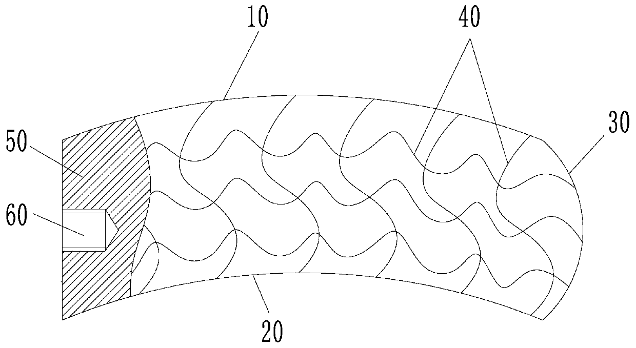
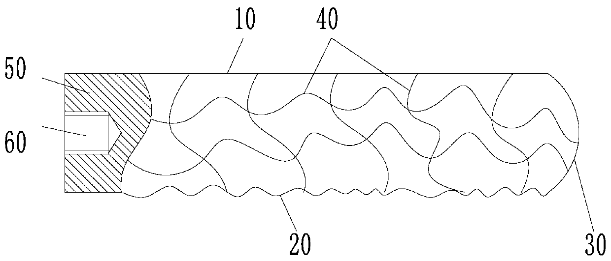
[0038] The intervertebral cage of this embodiment adjusts the shapes of the first plate body 10 and the second plate body 20, specifically as Figure 4As shown, the first plate body 10 of this embodiment is in the shape of a corrugated plate, and the second plate body 20 is in the shape of a flat plate. In the initial state, the first plate body 10 extends along a curve, and the second plate body 20 is in a curved state, so that the body of the intervertebral cage is curved; in the assembled state, the first plate body 10 shrinks and extends along a straight line, and the second plate body 20 shrinks and extends along a straight line. The second plate body 20 is straightened in a straight state, so that the body of the intervertebral cage is straight.
Embodiment 3
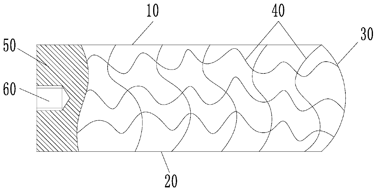
[0040] The intervertebral cage of this embodiment adjusts the shapes of the first plate body 10 and the second plate body 20, specifically as Figure 5 As shown, the first plate body 10 and the second plate body 20 of this embodiment are both in the shape of a wave plate. In the initial state, the first plate body 10 and the second plate body 20 extend along a curve, so that the body of the intervertebral fusion cage The overall shape is curved; in the assembled state, the first plate body 10 shrinks and the second plate body 20 stretches so that the body of the intervertebral cage is straight as a whole.
PUM
 Abstract
Description
Claims
Application Information