Calibration point identification method and storage medium

A recognition method and a calibration point technology, applied in the field of calibration point recognition

Inactive Publication Date: 2020-05-12
广东星舆科技有限公司
View PDF0 Cites 2 Cited by
  • Summary
  • Abstract
  • Description
  • Claims
  • Application Information

AI Technical Summary

Problems solved by technology

[0005] In summary, in the prior art, camera calibration lacks an automatic and simple solution for identifying calibration points

Method used


Image

  • Calibration point identification method and storage medium
  • Calibration point identification method and storage medium
  • Calibration point identification method and storage medium

Examples


Embodiment Construction

[0030] The technical means or technical effects involved in the present invention will be further described below. Obviously, the provided examples are only some implementations of the present invention, not all of them. All other embodiments that can be obtained by those skilled in the art based on the embodiments of the present invention and the explicit or implied representations of the pictures and texts will fall within the protection scope of the present invention.

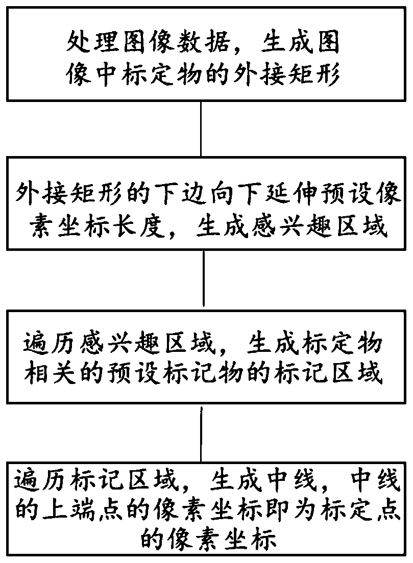
[0031] On the general idea, the present disclosure discloses a method for identifying a calibration point, which includes the following steps: processing image data to generate a circumscribing rectangle of the calibration object in the image; the lower side of the circumscribing rectangle extends downward to a preset pixel coordinate length to generate an object of interest area; traverse the region of interest to generate the marked area of ​​the preset marker related to the calibration object; traverse the...


PUM


Abstract

The invention relates to the technical field of image processing, and discloses a calibration point identification method, which comprises the steps of processing image data, and generating an external rectangle of a calibration object in an image, wherein the lower edge of the circumscribed rectangle extends downwards by a preset pixel coordinate length to generate a region of interest; traversing the region of interest to generate a marking region of a preset marker related to the calibration object; traversing the marking area to generate a middle line, and taking the pixel coordinate of the upper end point of the middle line as the pixel coordinate of the calibration point. The method has the advantages that manual interaction is reduced, and effective and automatic identification of the calibration points is achieved.

Description

technical field [0001] The invention relates to the field of image processing, in particular to a calibration point recognition technology in the field of image processing. Background technique [0002] Vision is an important means for humans to observe and understand the world, accounting for 70% of the information humans obtain from the external environment. Human beings use their eyes to obtain the light reflected by surrounding objects or emitted by themselves. The light forms an image on the retina and is transmitted to the brain through nerve fibers. The brain processes and understands the visual information and finally forms vision. Computer vision simulates the function of human vision, uses cameras to obtain images of the surrounding environment, and uses computers to process images. Computer vision can accomplish tasks that human vision is not capable of, such as accurate measurement of the size and distance of the object to be measured. Computer vision technolog...

Claims


Application Information

Patent Timeline
Patent Type & Authority Applications(China)
IPC IPC(8): G06T7/80
CPCG06T7/80G06T2207/20081G06T2207/20084G06T2207/30248
Inventor 袁超峰刘福明韩雨
Owner 广东星舆科技有限公司
Why Eureka
Try Eureka