Soil treatment and remediation device

A soil and power device technology, applied in the field of soil remediation and remediation devices, can solve the problems of low efficiency, slow speed, low efficiency, etc., and achieve the effect of improving the efficiency of soil remediation and improvement and increasing the amount of

Inactive Publication Date: 2020-05-15
李国宁
View PDF7 Cites 2 Cited by
  • Summary
  • Abstract
  • Description
  • Claims
  • Application Information

AI Technical Summary

Problems solved by technology

At present, the first method is mostly used. By matching the corresponding soil improvement and restoration solution, the existing form of pollutants in the soil or the combination with the soil can be changed. It is possible to dig a hole and inject the soil improvement and restoration solution ...

Method used


Image

  • Soil treatment and remediation device
  • Soil treatment and remediation device
  • Soil treatment and remediation device

Examples


Embodiment 1

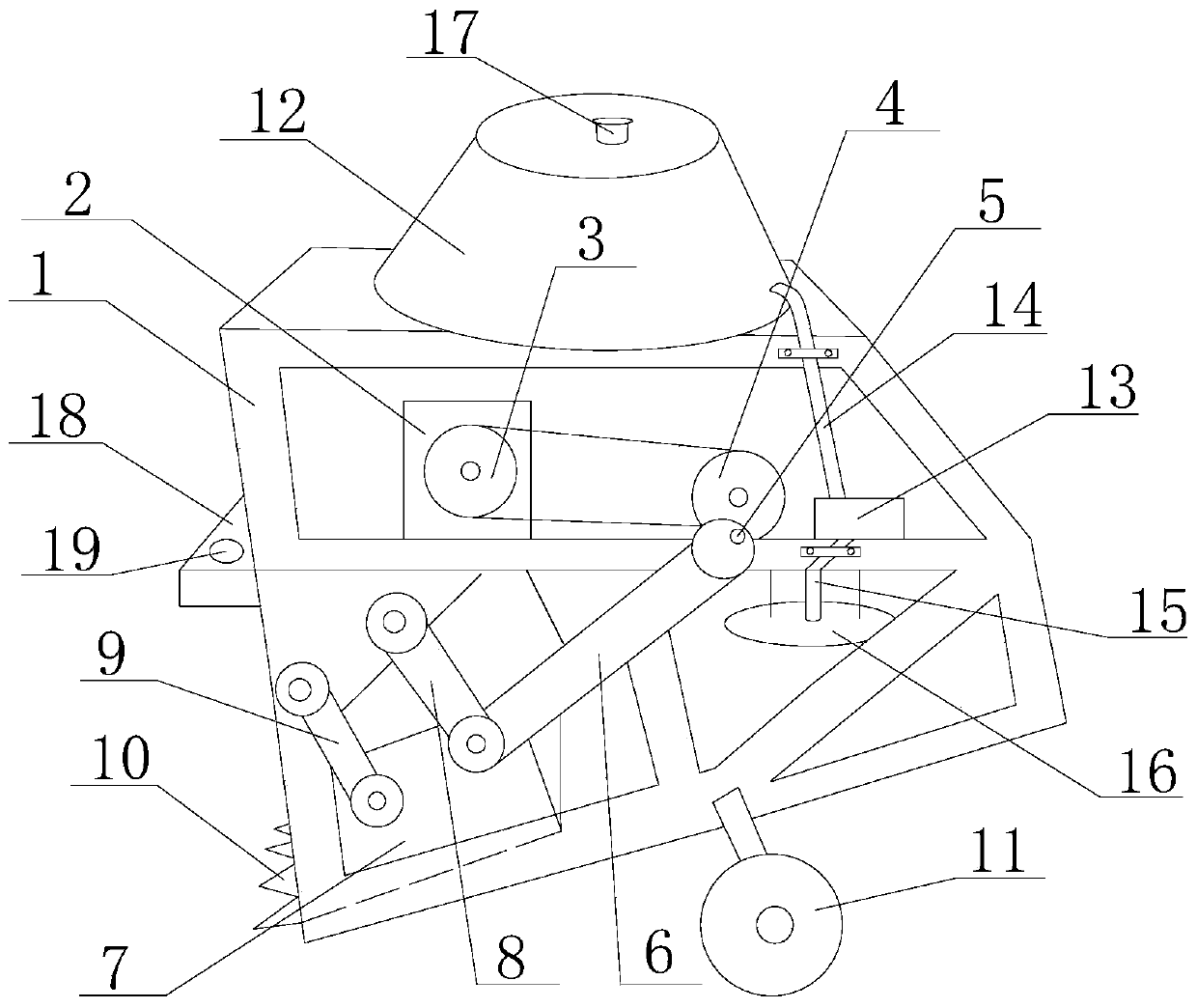
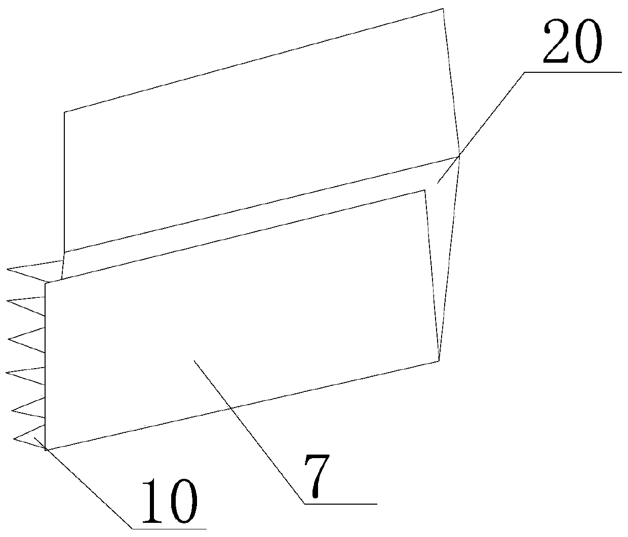
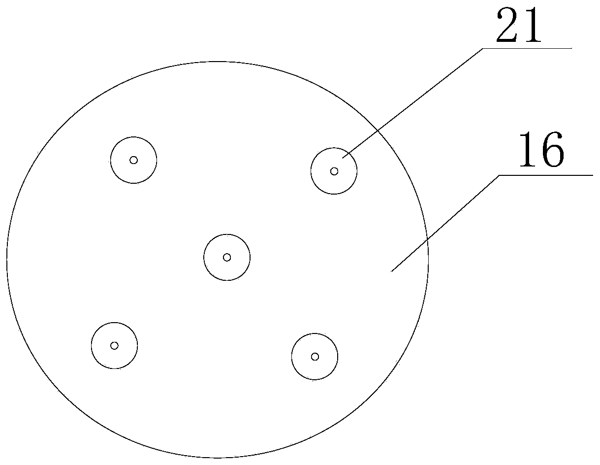
[0023] Such as Figure 1 to Figure 3 As shown, the soil treatment and restoration device of the present invention includes a frame 1 and a roller 11 arranged at the bottom of the frame 1, on which a power unit, an excavation device and a soil improvement and restoration liquid spraying device are arranged; The digging device includes a digging bucket arranged at the left end of the bottom of the frame 1, and the digging bucket includes a bottom plate 20, vertical plates 7 are arranged at the front and rear ends of the bottom plate 20, and digging teeth 10 are arranged at the left end, so that the left end of the digging bucket It forms the soil inlet, and the right end forms the soil outlet; it also includes a first connecting rod 9 and a transmission connecting rod 6, one end of the first connecting rod 9 is hinged on the frame 1, and the other end is hinged on the left part of the vertical plate 7, so One end of the transmission connecting rod 6 is transmitted with the power...

Embodiment 2

[0025] On the basis of the above embodiments, in order to further better implement the present invention, when the frame 1 is placed horizontally, the angle between the bottom plate 20 and the horizontal plane is 10° to 30°. After designing like this, excavating tooth 10 and a suitable angle constantly carry out soil excavation, can improve efficiency greatly.

Embodiment 3

[0027] On the basis of the above-mentioned embodiments, in order to further better implement the present invention, it also includes a second connecting rod 8, one end of which is hinged with the frame 1, and the other end is hinged with the transmission connecting rod 6 using a common hinge shaft. On the right of riser 7. After this design, the mechanical stability of the whole excavating device is improved and the service life is prolonged.


PUM


Abstract

The invention relates to territorial resource treatment, and concretely relates to a soil treatment and remediation device capable of improving soil remediation and improvement efficiency. An excavating device comprises an excavating bucket arranged at the left end of the bottom of the rack, the excavating bucket comprises a bottom plate, vertical plates are arranged at the front end and the rearend of the bottom plate, and excavating teeth are arranged at the left end of the bottom plate; and one ends of first connecting rods are hinged to a rack, the other ends of the first connecting rodsare hinged to the left parts of the vertical plates, one ends of transmission connecting rods are in transmission with a power device, and the other ends of the transmission connecting rods are hingedto the right parts of the vertical plates. The rack, rolling wheels, the power device, an excavating device and a soil improvement and remediation liquid spraying device are matched to make the soilimprovement and remediation liquid spraying device continuously spray, a soil improvement and remediation liquid medicine is sprayed to soil before excavation, and after the power device drives the excavating device to excavate the soil, the soil improvement and remediation liquid spraying device continues to spray the excavated soil, and the amount of soil absorbing the soil improvement and remediation liquid can be increased, so the soil remediation and improvement efficiency is greatly improved.

Description

technical field [0001] The invention relates to land resources management, in particular to a soil treatment and restoration device capable of improving the efficiency of soil restoration and improvement. Background technique [0002] Soil pollution in China has threatened the sustainable use of land resources and the ecological security of agricultural products. The farmland polluted by organic pollutants in the country has reached 36 million hectares. The types of pollutants include petroleum, polycyclic aromatic hydrocarbons, pesticides, and organic chlorine. It also pollutes a large area of ​​land; in the Shenfu petroleum sewage irrigation area, the content of polycyclic aromatic hydrocarbons in the surface layer and bottom soil both exceeds 600mg / kg, causing serious pollution of crops and groundwater. There are 20 million hectares of land polluted by heavy metals across the country, of which more than 700,000 hectares are seriously polluted, and 130,000 hectares of whi...

Claims


Application Information

Patent Timeline
IPC IPC(8): B09C1/08
CPCB09C1/08B09C2101/00
Inventor 李国宁
Owner 李国宁
Why Eureka
Try Eureka