Ship life raft release device

A release device and life raft technology, which is applied in the field of ships, can solve the problems of the life raft release device being complicated in structure, affecting the reliability of blasting, and high cost of manual installation, and achieving the effects of simple structure, convenient production and improved safety.

Pending Publication Date: 2020-05-15
CHIYANG ELECTRONICS SCI & TECH
View PDF0 Cites 2 Cited by
  • Summary
  • Abstract
  • Description
  • Claims
  • Application Information

AI Technical Summary

Benefits of technology

This invention relates to a mechanism for releasing or cutting out connections between two springs without triggering explosions caused by excessive hydraulic pressures during certain stages of operation. It uses a lower chamber with a pump connected through pipes to create high-pressure fluid within the system's interior space. An electric current flows from one side into another direction causing a decrease in resistance due to changes made across its components. To prevent this phenomenon, there are limits placed at both ends of each component called terminal posts where electrical connectors may pass through them. These limitations help keep the system safe even if some parts get damaged accidentally while still allowing enough power to operate properly.

Problems solved by technology

This patented technical problem addressed in this patents relates to an improved lifeline system used during rescue operations where there are many challengings such as slipping or getting stuck due to waves caused by heavy loads being carried overboard at sea level floors.

Method used


Image

  • Ship life raft release device
  • Ship life raft release device
  • Ship life raft release device

Examples


Embodiment Construction

[0030] Embodiments of the present invention are described in detail below, examples of which are shown in the drawings, wherein the same or similar reference numerals designate the same or similar elements or elements having the same or similar functions throughout. The embodiments described below by referring to the figures are exemplary only for explaining the present invention and should not be construed as limiting the present invention.

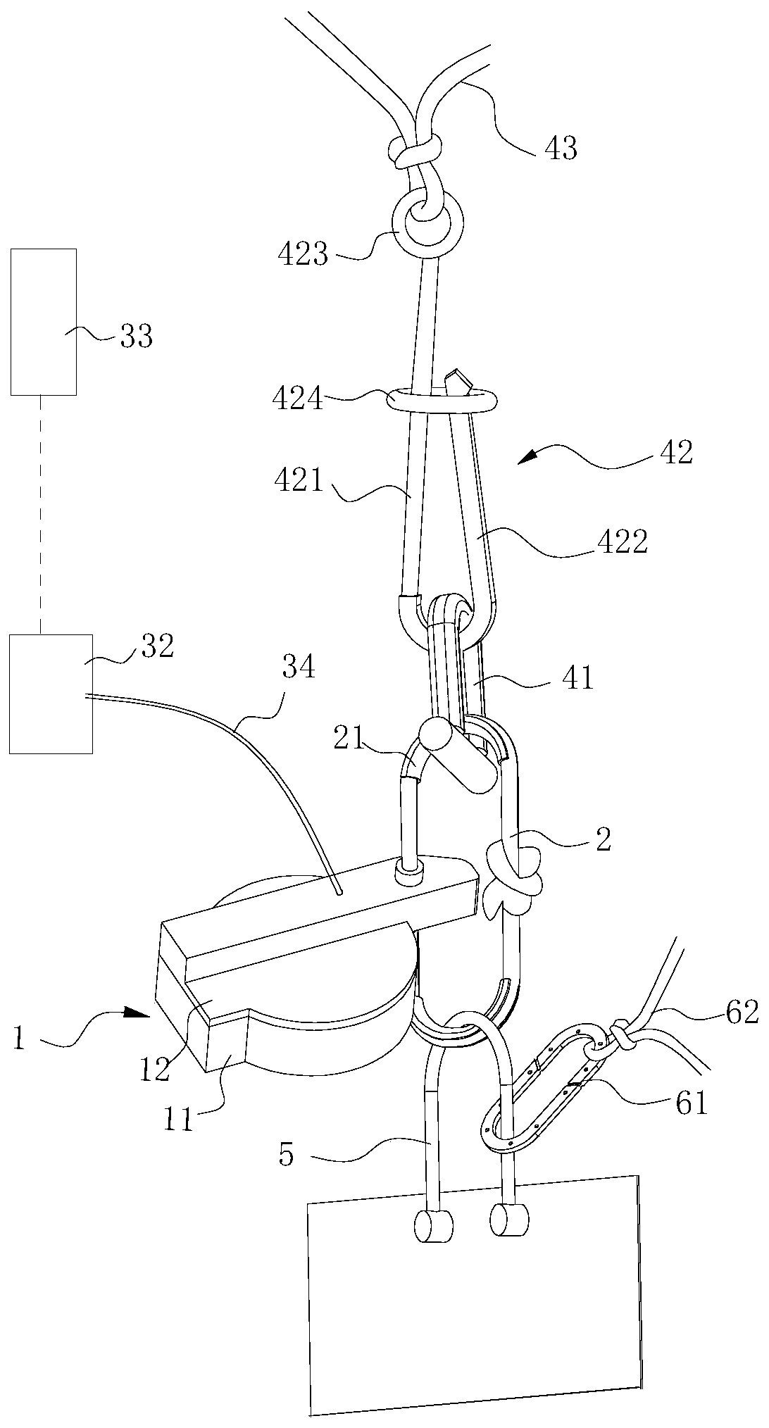
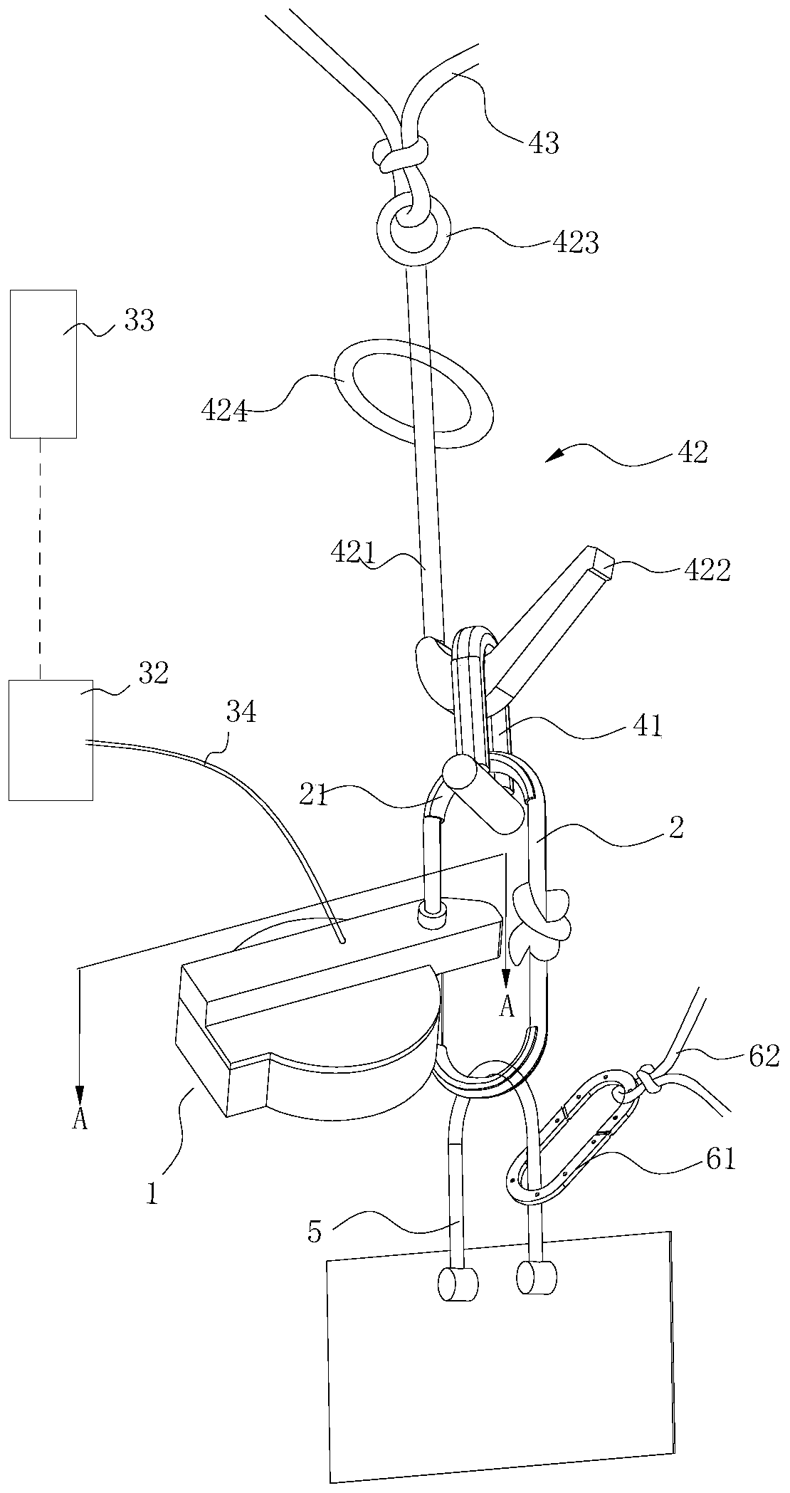
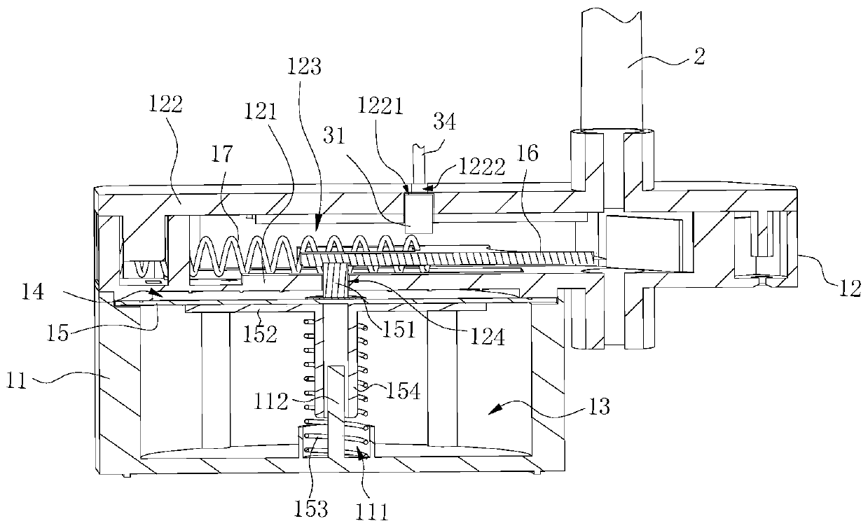
[0031] like Figures 1 to 6 Shown is a schematic structural view of an embodiment of the present application. As shown in the figure, the ship liferaft release device includes a release device 1, a first connecting rope 2 threaded on the release device 1, and connects the ship and the first connecting rope 2 The second connecting piece for connecting one end of the life raft and the first connecting piece for connecting the other end of the first connecting rope 2, the releaser 1 includes a lower cover 11 and an upper cover 12 that is cl...


PUM


Abstract

The invention relates to a ship life raft release device. The lifesaving device comprises a releaser, a first connecting rope arranged on the releaser in a penetrating mode, a second connecting piecefor connecting a ship with the first connecting rope, and a first connecting piece for connecting a lifesaving raft with the first connecting rope. The releaser comprises a lower cover and an upper cover; a pressure sensing film is arranged in the releaser, a cutter used for cutting off the first connecting rope and a first pushing part used for pushing the cutter to move towards the first connecting rope are arranged above the pressure sensing film, and a second pushing part capable of limiting the first pushing part and moving along with the pressure sensing film to relieve limiting of the first pushing part is arranged on the pressure sensing film; the release device further comprises a liquid electrolytic capacitor which is arranged on the upper cover and can push the pressure sensingfilm to move downwards during explosion, a main control unit which is connected with the liquid electrolytic capacitor to provide explosion overvoltage for the liquid electrolytic capacitor, and a remote controller which is used for sending an action instruction to the main control unit. The releasing device can release the life raft in various modes, and is convenient to use, safe and reliable.

Description


Claims


Application Information

Patent Timeline
Owner CHIYANG ELECTRONICS SCI & TECH
Why Eureka
Try Eureka