
Supporting device for hydraulic pipeline vibration test of aero-engine

A technology for aero-engine and vibration testing, applied in vibration testing, fluid pressure actuating devices, measuring devices, etc., can solve problems such as inability to simulate hydraulic system tests, difficult to explore, and inability to detect multi-space bending angle pipeline vibration signals.

Pending Publication Date: 2020-05-15
UNIV OF SCI & TECH LIAONING
View PDF1 Cites 6 Cited by
  • Summary
  • Abstract
  • Description
  • Claims
  • Application Information

AI Technical Summary

Problems solved by technology

However, because aviation hydraulic pipelines are limited and constrained by the space structure, it is difficult to collect and explore the vibration signals of hydraulic pipelines in actual engineering, especially for aviation hydraulic space pipelines and hydraulic bends of different diameters.
However, the commonly used hydraulic pipeline vibration test support can only detect the vibration signals of straight pipes and curved pipes in the plane range, and cannot detect the vibration signals of multi-space bending angle pipelines.
The Chinese patent with patent application number 201410467803.8 discloses "a hydraulic pipeline vibration test device with adjustable support stiffness". Continuous adjustment of support stiffness, installation and testing of hydraulic pipelines with complex structures of different lengths and angles, simulation of boundary stiffness of multi-section pipeline connections, but this technical solution can only be installed and tested for single-pipe structures, and cannot be used for multi-pipe structures at the same time Simulate tests on hydraulic systems with roads and different diameters
The test efficiency is low, and at the same time, it cannot truly simulate the actual working environment of the aviation hydraulic pipe bend

Method used


Image

  • Supporting device for hydraulic pipeline vibration test of aero-engine
  • Supporting device for hydraulic pipeline vibration test of aero-engine
  • Supporting device for hydraulic pipeline vibration test of aero-engine

Examples


Embodiment

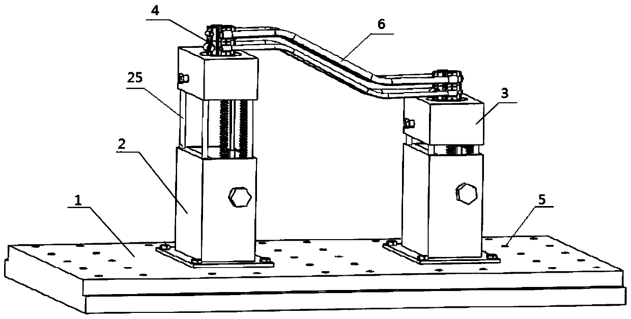
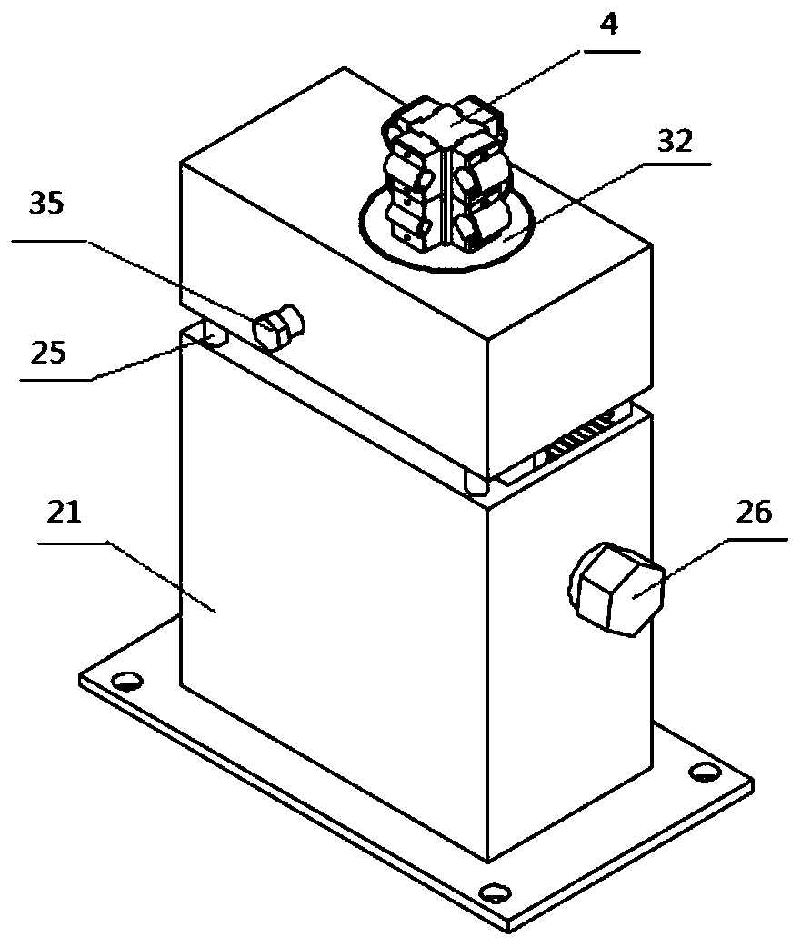
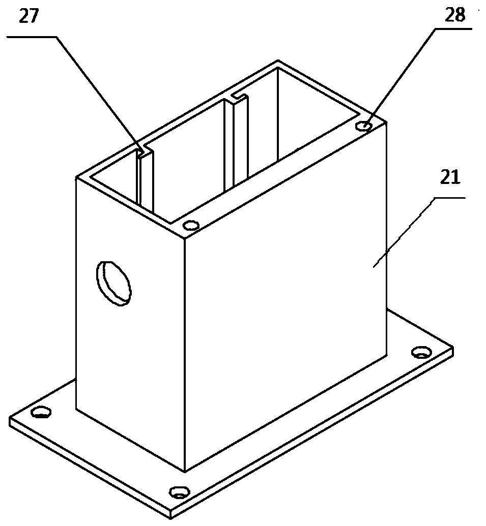
[0025] Such as figure 1 , for the use of the supporting device for the vibration test of the hydraulic pipeline of the aero-engine, select two lifting bases 2 according to the length and space shape of the pipeline under test 6, and fix the two lifting bases 2 on the bolt holes of the support base 1 5, then connect the tested pipeline 6 with the oil pump and fix it on the pipe clamp slider 42 of the corresponding aperture, adjust the height of the lifting base 2, adjust the angle of the rotating device 3, realize the support of the tested pipeline 6, and carry out pipeline Vibration test.


PUM


Abstract

The invention relates to a supporting device for a hydraulic pipeline vibration test of an aero-engine. The supporting device comprises a supporting base, lifting bases, rotating devices and hoop assemblies, wherein the supporting base is connected with the plurality of lifting bases through bolts, the top ends of the lifting bases are connected with the rotating devices, and the top ends of the rotating devices are connected with the hoop assemblies. According to the supporting device, installation and testing of complicated-structure hydraulic pipelines with different lengths, heights and space angles can be achieved, vibration characteristics of multiple pipeline connection can be simulated at the same time, and the device is suitable for high-efficiency simulation testing of multi-dimensional, multi-azimuth and different-diameter hydraulic systems in a laboratory. The device can be matched with a vibration testing bed to simulate a vibration basic environment of the hydraulic pipelines, an actual working environment of aviation hydraulic pipelines is efficiently simulated really, so that a vibration mechanism and dynamic characteristics of pipeline vibration in an aviation hydraulic pipeline system are fully understood, and support is provided for monitoring and diagnosis of the hydraulic pipelines by utilizing big data.

Description

technical field [0001] The invention relates to the technical field of simulated hydraulic pipeline vibration tests, in particular to a supporting device for vibration tests of hydraulic pipelines of aeroengines. Background technique [0002] At present, the aviation hydraulic system is developing in the direction of high speed and high pressure. With the continuous improvement of the pressure system, the vibration characteristics of the aviation hydraulic piping system are more complex, and it has become a worldwide problem for its stable flight. At the same time, aviation hydraulic pipelines are affected by factors such as oil pulsation, pressure, and structural parameters, resulting in the vibration characteristics of the pipeline directly affecting the stability and reliability of the entire system. Since the vibration is an important parameter in the status monitoring of the aviation hydraulic pipeline system, the vibration monitoring of the hydraulic pipeline under tes...

Claims


Application Information

Patent Timeline
Patent Type & Authority Applications(China)
IPC IPC(8): F15B19/00G01M7/02
CPCF15B19/00G01M7/02
Inventor 于晓光刘佳琪刘佳鸣孙杰薛政坤窦金鑫杨同光范玉鑫段宝嘉
Owner UNIV OF SCI & TECH LIAONING
Learn More