
Power supply device and power supply method

A power supply device and power supply technology, applied in the direction of circuit devices, emergency protection circuit devices, emergency power arrangements, etc., can solve problems such as arcing conditions, high-frequency noise, and affecting the operation of peripheral circuits, so as to prevent arcing and improve work efficiency Effect

Active Publication Date: 2022-04-29
WIWYNN CORP
View PDF5 Cites 0 Cited by
  • Summary
  • Abstract
  • Description
  • Claims
  • Application Information

AI Technical Summary

Problems solved by technology

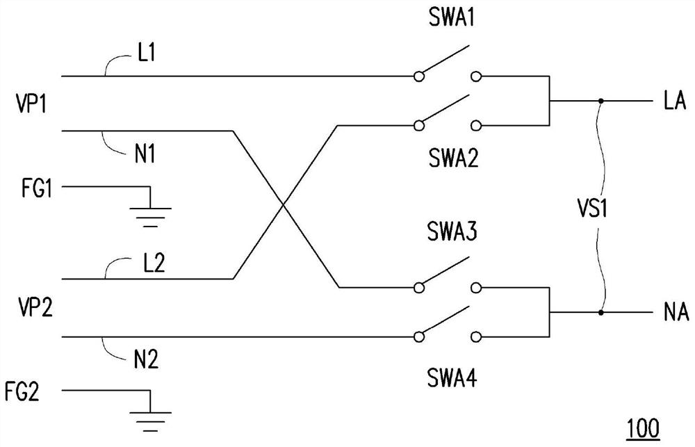
[0004] It is worth noting that when the switches SWA1~SWA4 are switching, the current in the circuit will cause arcing.
Moreover, the bouncing phenomenon during the switching process of the switches SWA1~SWA4 will generate high-frequency noise correspondingly, and affect the operation of itself and surrounding circuits

Method used


Image

  • Power supply device and power supply method
  • Power supply device and power supply method
  • Power supply device and power supply method

Examples


Embodiment Construction

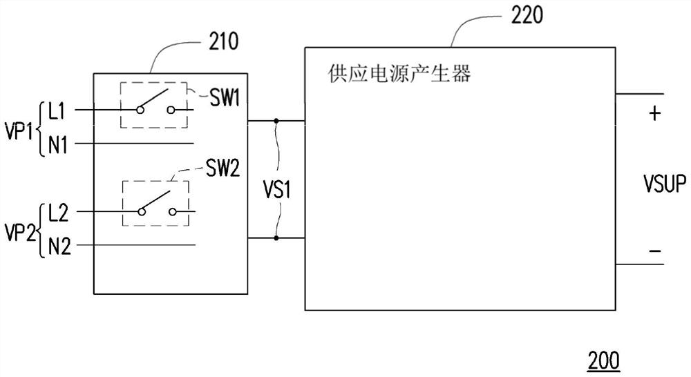
[0041] Please refer to figure 2 , figure 2 A schematic diagram of a power supply device according to an embodiment of the present invention is shown. The power supply device 200 includes a power switch 210 and a power supply generator 220 . The power switch 210 can be an automatic power switch, and has switches SW1 and SW2. The switch SW1 is coupled to the live line L1, and the switch SW2 is coupled to the live line L2. The power switch 210 receives the power VP1 through the live line L1 and the neutral line N1 , and the power switch 210 receives the power VP2 through the live line L2 and the neutral line N2 . Wherein, the power switcher 210 receives the power VP1 through the switch SW1 to generate the selected power VS1 , or receives the power VP2 through the switch SW2 to generate the selected power VS1 .

[0042] The power supply generator 220 is coupled to the power switch 210 . The power supply generator 220 receives the selected power VS1 , and performs voltage co...


PUM


Abstract

The invention provides a power supply device and a power supply method. The power supply device includes a power switch and a power supply generator. The power switcher receives the first power and the second power respectively through the first switch and the second switch. The supply power generator performs a voltage conversion operation on the first power supply or the second power supply to generate supply power. When the supply power generator determines that the first power supply is powered off, in the first time interval, the first switch is turned off and the supply power generator stops the voltage conversion operation. In the second time interval, the second switch is turned on, and after the second switch is turned on, the supply power generator re-executes the voltage conversion operation to generate the supply power. The invention has the beneficial effects of effectively reducing the arc phenomenon generated when the power supply is switched and avoiding the influence caused by the switch bouncing.

Description

technical field [0001] The present invention relates to a power supply device and a power supply method, and in particular to a power supply device and a power supply method for an uninterruptible power supply system. Background technique [0002] In the known technical field, the power supply device of the uninterruptible power system uses an automatic power transfer switch (Automatic Transfer Switch, ATS) to switch between the main power supply and the auxiliary power supply. Please refer to figure 1 The circuit diagram of the automatic power transfer switch shown. The known automatic power switch 100 includes a plurality of switches SWA1 - SWA4 , wherein the switches SWA1 , SWA2 are respectively coupled to the live wires L1 , L2 , and the switches SWA3 , SWA4 are respectively coupled to the neutral wires N1 , N2 . The live wire L1 , the neutral wire N1 and the ground wire FG1 are used to receive the power VP1 , and the live wire L2 , the neutral wire N2 and the ground w...

Claims


Application Information

Patent Timeline
Patent Type & Authority Patents(China)
IPC IPC(8): H02J9/06
CPCH02J9/061H02M1/4225H02M1/10Y02B70/10H02J9/062H02J9/068H02H7/10H02J9/06
Inventor 许冠伟
Owner WIWYNN CORP
Learn More