
Regional lock-state control system

A state-controlled, regional technology

Pending Publication Date: 2020-05-15
CARRIER CORP
View PDF4 Cites 2 Cited by
  • Summary
  • Abstract
  • Description
  • Claims
  • Application Information

AI Technical Summary

Problems solved by technology

Unfortunately, once a lockdown event has occurred, people's locations in the area may not be known

Method used


Image

  • Regional lock-state control system
  • Regional lock-state control system
  • Regional lock-state control system

Examples


Embodiment Construction

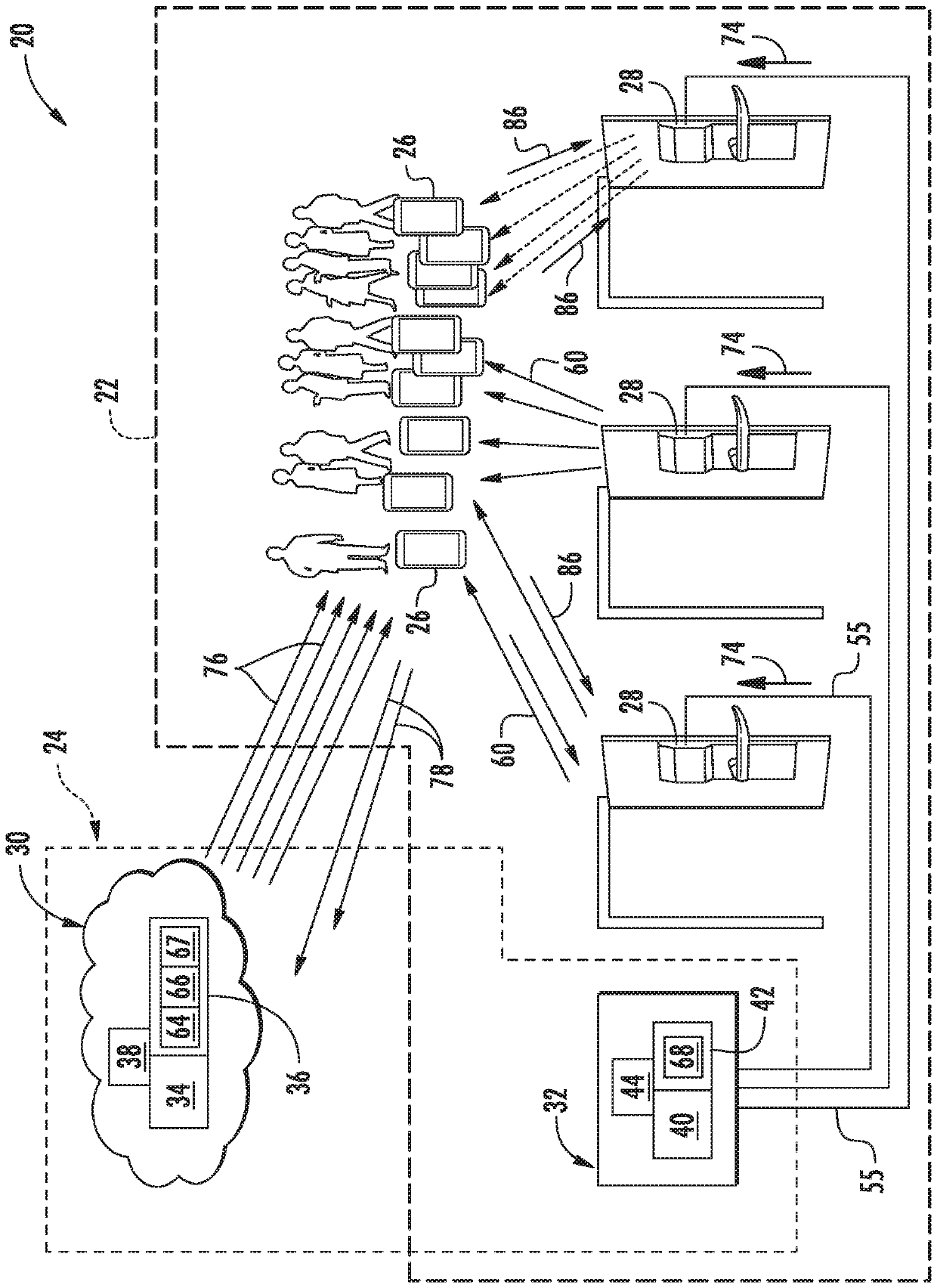
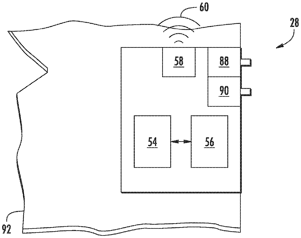
[0030] refer to figure 1 , a zone lock status control system 20 may be operable within a zone 22 and may include a control device 24 , a plurality of mobile devices 26 and a plurality of lock assemblies 28 which may be dispersed throughout the zone 22 . The zone lock status control system 20 may be a zone lock system, or alternatively, a zone unlock system. Examples of areas 22 may include office buildings, student campuses, hotels, among others. Control device 24 may include a controller 32 and a server 30 , which may be local and located within area 22 . Server 30 may run remotely or locally, and / or may be cloud or web-based. In one example, server 30 may not communicate directly with local controller 32 . It is further contemplated and understood that controller 32 may be integral to server 30 (ie, may share the same processor and computer-readable storage medium). While lock assembly 28 is shown as a door lock assembly, non-limiting examples of lock assembly 28 may als...


PUM


Abstract

A regional lock-state control system for operation within a region, includes a server, a plurality of mobile devices and a plurality of lock assembles. The server is configured to initiate a lock-state event. The mobile devices are each configured to receive a wireless lock-state directive from the server upon the lock-state event, and send a wireless lock lock-state directive to the server. The lock assemblies are each configured to receive a lock-state command associated with the lock-state directive from the plurality of mobile devices, and are each configured to transmit an advertisement that includes data on the lock-state.

Description

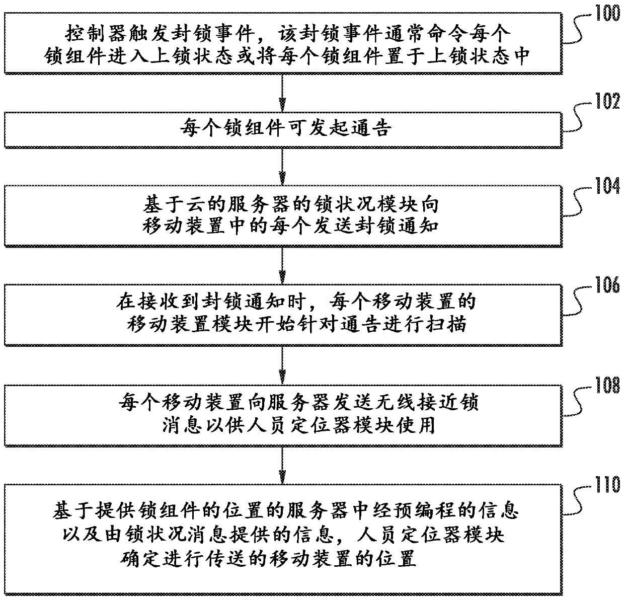
Background technique [0001] The present disclosure relates to a lock system, and more particularly, to a zone lock-state control system generally operable within a predefined zone. [0002] Traditionally, a zone lock status control system, such as a lockdown system, can be used in predefined zones. Examples of such areas may be buildings, university campuses, and others. All locks (eg door locks) that are part of the locking system can be locked automatically via the central controller upon predefined events. Unfortunately, once a lockdown event has occurred, it may not be known where people are in the area. Contents of the invention [0003] A zone lock status control system for operation within a zone, a zone lock status control system according to a non-limiting embodiment of the present disclosure includes: a server configured to initiate a lock status event; a plurality of mobile devices , each of the plurality of mobile devices is configured to receive a wireless lo...

Claims


Application Information

Patent Timeline
Patent Type & Authority Applications(China)
IPC IPC(8): G07C9/27G07C9/28G07C9/29G07C9/00H04W4/02
CPCG07C9/00571H04W4/02G07C2209/62G07C2209/63G07C9/00309G07C9/29G07C9/27G07C9/28H04W12/30H04W12/64G06F21/44H04W12/08
Inventor A.屈恩斯S.梅农J.J.哈克马
Owner CARRIER CORP
Learn More