A Preliminary Test Method for Floor Vibration Comfort Based on Heart Rate Variation
What is AI technical title?
AI technical title is built by Patsnap AI team. It summarizes the technical point description of the patent document.
A technology of preliminary testing and heart rate change, applied in the field of testing floor comfort, can solve problems affecting work and life, and achieve the effects of reducing evaluation costs, saving time costs, and comprehensively utilizing resources
Active Publication Date: 2021-10-22
HEFEI UNIV OF TECH
View PDF13 Cites 0 Cited by
Summary
Abstract
Description
Claims
Application Information
AI Technical Summary
This helps you quickly interpret patents by identifying the three key elements:
Problems solved by technology
Method used
Benefits of technology
Problems solved by technology
[0004] Therefore, if a building is built with a floor with unknown comfort index, once the comfort of the floor does not meet the standard, it will seriously affect the work and life of the people in the building. It is very necessary to design a method to evaluate the vibration comfort of the floor
Method used
Image
Click on the blue label to locate the original text in one second.
Reading with bidirectional positioning of images and text.
Examples
Embodiment 1
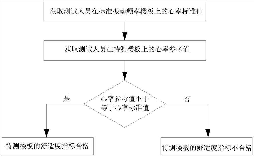
[0046] A preliminary test method for floor vibration comfort based on heart rate variation, such as figure 1 shown, including the following steps:
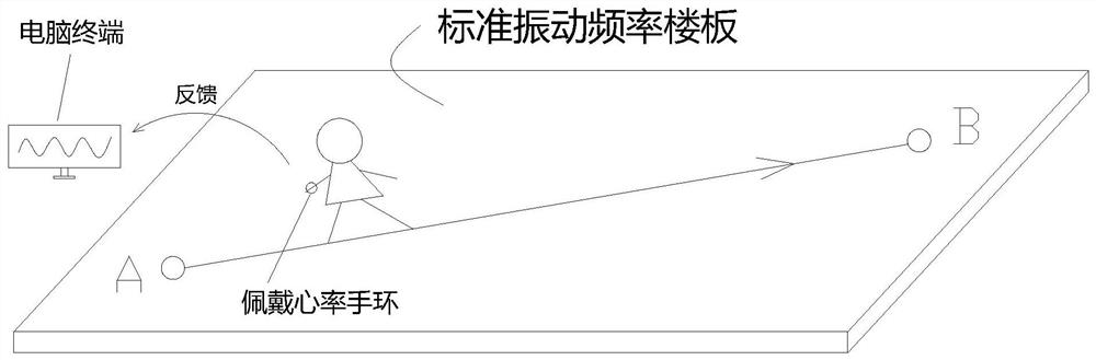
[0047] S1. Obtain the standard heart rate value of the tester on the standard vibration frequency floor. The heart rate standard value is used to reflect the comfort brought by the standard vibration frequency floor to the tester. The standard vibration frequency of the floor can be 3Hz, or 4Hz, 8Hz, 10Hz, 15Hz. In this embodiment, the standard vibration frequency of the floor is 3 Hz. The age of the tester is 18 to 50 years old, the weight of the tester is 45kg to 70kg, and the height is 150cm to 180cm. The specific steps are as follows:
[0048] like figure 2 As shown, design a floor with the natural frequency as the critical value, the boundary condition is rigid connection around, and the working condition X1 is set: ordinary people walk from point A to point B along the span direction of the floor at a walking frequency o...
Embodiment 2
[0059] On the basis of Embodiment 1, the standard value of the heart rate in step S1 can also be:
[0060]
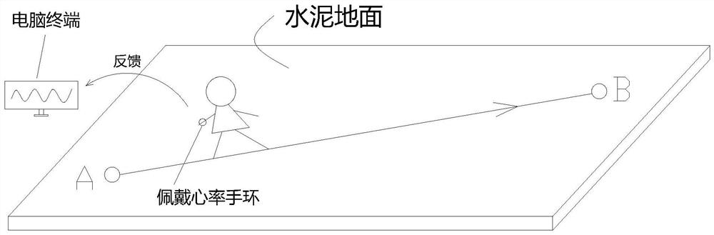
[0061] in, n is the total number of experiments, in this embodiment, the value of n is 10, z ij is the peak heart rate of the tester at the step frequency i on the concrete floor in the jth test, Y i is the peak heart rate of the tester at the step frequency i on the standard vibration frequency floor, for The absolute value of , K i is the standard value of heart rate at cadence i, where cadence i is i steps per unit time.
[0062] The heart rate reference value obtained in step S2 may also be:
[0063]
[0064] y i is the peak heart rate of the tester when the stride frequency i is on the floor to be tested, for The absolute value of , k i is the heart rate reference value at cadence i.
PUM
Abstract
The invention relates to the field of testing floor comfort, in particular to a preliminary testing method for floor vibration comfort based on heart rate changes. The heart rate standard value of the tester on the standard vibration frequency floor is obtained, and the heart rate standard value is used to reflect the comfort level of the standard vibration frequency floor to the tester. The heart rate reference value of the tester on the floor to be tested is obtained, and the heart rate reference value is used to reflect the comfort level of the tester brought by the floor to be tested. If the heart rate reference value is less than or equal to the heart rate standard value, the comfort index of the floor to be tested is qualified; otherwise, the comfort index of the floor to be tested is unqualified. Taking the comfort level of the testers on the floor with the standard vibration frequency as the reference standard, the comfort level of the testers on the floor to be tested with an unknown vibration frequency is compared with the standard comfort level, so as to judge whether the floor to be tested meets the standard, and prevent the building from adopting unsuitable Standard floor slabs, causing discomfort to occupants.
Description
technical field [0001] The invention relates to the field of testing floor comfort, in particular to a preliminary testing method for floor vibration comfort based on heart rate changes. Background technique [0002] With the continuous improvement of engineering technology, the popularization and application of steel structures and the development of lightweight and high-strength materials, various new structural systems such as suspension structural systems and long-span structural systems have been widely used. Damping trend. [0003] Due to the complexity of structural systems such as suspended structural systems and long-span structural systems, the natural vibration frequency of the structure itself is low. When the frequency of pedestrian load excitation is similar to the natural vibration frequency of the floor, it will arouse a large vibration response of the floor, making people It resonates with the floor and affects people's normal life and production. Therefore...
Claims
Application Information
Patent Timeline
Application Date:The date an application was filed.
Publication Date:The date a patent or application was officially published.
First Publication Date:The earliest publication date of a patent with the same application number.
Issue Date:Publication date of the patent grant document.
PCT Entry Date:The Entry date of PCT National Phase.
Estimated Expiry Date:The statutory expiry date of a patent right according to the Patent Law, and it is the longest term of protection that the patent right can achieve without the termination of the patent right due to other reasons(Term extension factor has been taken into account ).
Invalid Date:Actual expiry date is based on effective date or publication date of legal transaction data of invalid patent.

