MEMS loudspeaker and manufacturing method thereof

A speaker and driver technology, applied in electrostatic transducer speakers, microphones, sensors, etc., can solve the problems of large vibration amplitude of the diaphragm, low sound output of the speaker, and small vibration amplitude of the surrounding parts, so as to improve the sound output and improve the sound. output effect

Active Publication Date: 2020-05-19
AAC TECH NANJING
View PDF7 Cites 11 Cited by
  • Summary
  • Abstract
  • Description
  • Claims
  • Application Information

AI Technical Summary

Problems solved by technology

[0003] In the prior art, the diaphragm in the loudspeaker usually produces sound through the vibration of the diaphragm, but because the edges of the diaphragm usually need to be fixed to other components, the center of the diaphragm vibrates with a large amplitude, while the peripheral part vibrates small, resulting in lower sound output from the speaker

Method used


Image

  • MEMS loudspeaker and manufacturing method thereof
  • MEMS loudspeaker and manufacturing method thereof
  • MEMS loudspeaker and manufacturing method thereof

Examples


Embodiment 1

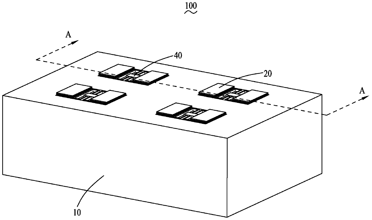
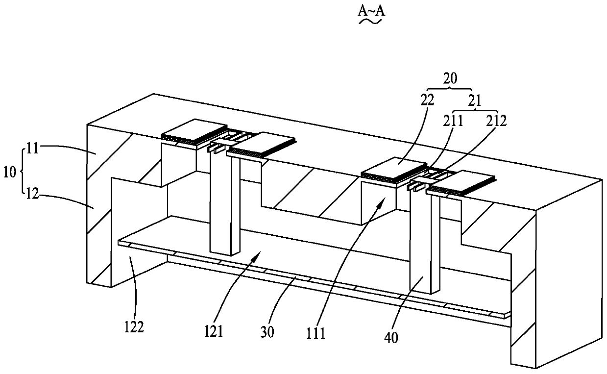
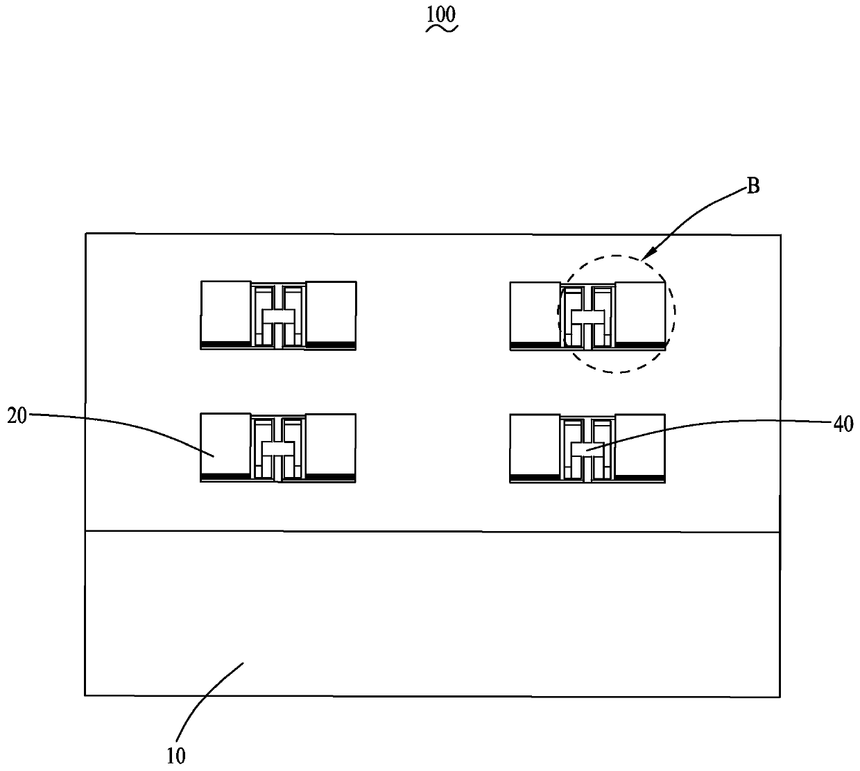
[0040] see Figure 1 to Figure 4, a MEMS speaker 100 provided according to an embodiment of the present invention includes a base 10, a vibrating assembly 20, a diaphragm 30, and a connecting rod 40. The base 10 includes a base 11 and a support seat 12, and the support base 12 is formed from one side of the base 11 Extending away from the base 11, the base 11 is provided with a first cavity 111 along its thickness direction, which is also the extension direction of the support seat 12. Body 111 communicates with the second cavity 121, the inner diameter of the first cavity 111 along the direction perpendicular to the thickness of the base 11 is smaller than the second cavity 121, that is, the profile of the first cavity 111 is smaller than the second cavity 121, the vibration The component is fixed on the base 11 and covers at least part of the first cavity 111, one end of the connecting rod 40 is connected to the vibrating component 20, and the other end extends through the f...

Embodiment 2

[0075] see Figure 6 Compared with the MEMS speaker 100 provided in Embodiment 1, the MEMS speaker 200 provided in this embodiment is: the base 11' of this embodiment is provided with three first cavities 111' at intervals, and the three first cavities 111' are along the The MEMS speakers 200 are equally spaced along the length direction. It can be understood that the number of first cavities 111 ′ is not limited to three, for example, one, two or other numbers of multiples are also possible.

Embodiment 3

[0077] see Figure 7 Compared with the MEMS speaker 100 provided by Embodiment 1, the MEMS speaker 300 provided in this embodiment is cylindrical, and the vibration member 21 "is a cantilever beam form, and three The first cavities 111", the three first cavities 111" are equally spaced along the circumference of the base 11", and the angle between any two adjacent cantilever beams is 120°. It can be understood that the first The number of a cavity 111" is not limited to three, for example, one, two or other numbers of multiples are also possible.


PUM


Abstract

The invention discloses an MEMS loudspeaker and a manufacturing method thereof. The MEMS loudspeaker comprises a substrate, a vibration assembly, a diaphragm and a connecting rod, wherein the base comprises a substrate and a supporting seat extending from one side of the substrate, and a first cavity is formed in the base body in the thickness direction in a penetrating mode; the supporting seat is annular and defines a second cavity communicated with the first cavity, and the inner diameter of the first cavity in the direction perpendicular to the thickness direction is less than that of thesecond cavity; the vibration assembly is fixed to the base and at least covers part of the first cavity; one end of the connecting rod is connected with the vibration assembly, and the other end of the connecting rod extends to the second cavity through the first cavity and is connected with the diaphragm; and the diaphragm is suspended in the second cavity and spaced from the inner wall of the supporting base. According to the MEMS loudspeaker provided by the invention, the diaphragm is driven by the vibration assembly to perform piston motion to generate sound, so that more air with larger volume can be exhausted in unit time, and the sound output of the MEMS loudspeaker is improved.

Description

【Technical field】 [0001] The invention relates to the technical field of acoustic-electric conversion, in particular to a MEMS speaker and a method for manufacturing the MEMS speaker. 【Background technique】 [0002] A speaker is a transducer device that converts electrical signals into sound signals. It is widely used in various audio and mobile terminal equipment. The performance of the speaker will directly affect the sound quality of the audio or mobile terminal equipment. [0003] In the prior art, the diaphragm in the loudspeaker usually produces sound through the vibration of the diaphragm, but because the edges of the diaphragm usually need to be fixed to other components, the center of the diaphragm vibrates with a large amplitude, while the peripheral part vibrates small, resulting in lower sound output from the speaker. [0004] Therefore, it is necessary to provide an improved speaker to solve the above problems. 【Content of invention】 [0005] One object of t...

Claims


Application Information

Patent Timeline
Patent Type & Authority Applications(China)
IPC IPC(8): H04R19/00H04R19/02H04R31/00
CPCH04R19/005H04R19/02H04R31/00H04R2201/003
Inventor 程诗阳李杨但强朱国
Owner AAC TECH NANJING
Why Eureka
Try Eureka