Energy effecient blow molder control

A molding machine, controller technology, applied in the direction of digital control, electrical program control, general control system, etc.

Active Publication Date: 2020-05-19
AGR INT
View PDF22 Cites 0 Cited by
  • Summary
  • Abstract
  • Description
  • Claims
  • Application Information

AI Technical Summary

Problems solved by technology

These systems improve the quality of container production by removing containers with randomly occurring damage, inclusions, and poorly formed containers, but have had limited success in addressing process-related issues that drive container quality and performance

Method used


Image

  • Energy effecient blow molder control
  • Energy effecient blow molder control
  • Energy effecient blow molder control

Examples


Embodiment Construction

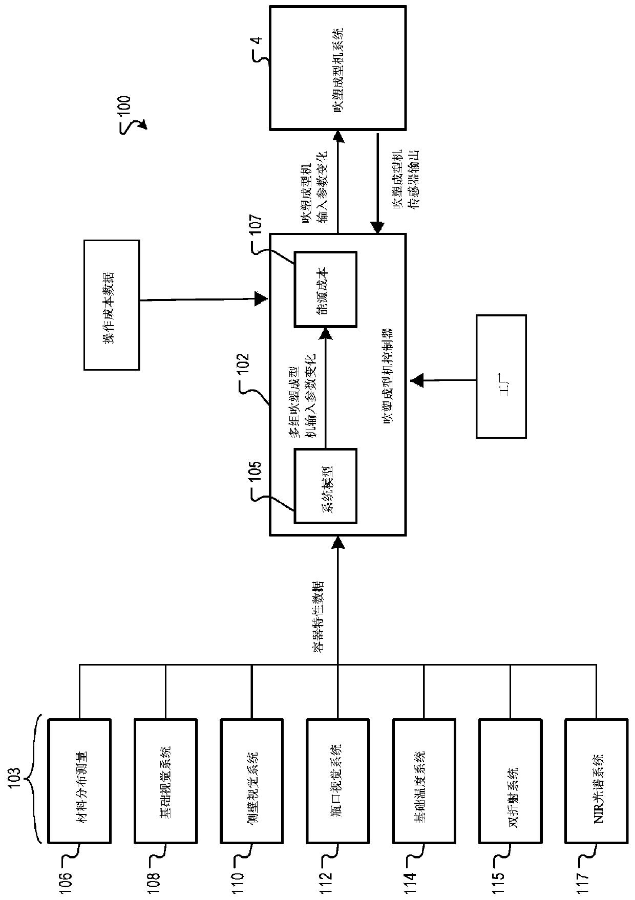
[0027] Various embodiments described herein relate to systems and methods for improving the efficiency (eg, energy efficiency) of blow molding machine controllers. The blow molding machine controller executes a system model that correlates changes in the input parameters of the blow molding machine with the characteristics of the container produced by the blow molding machine. In one embodiment, the operating cost module of the blow molding machine controller evaluates changes in multiple sets of input parameters generated by the system model based on energy and / or other similar costs. The blow molding machine controller implements a set of blow molding machine input parameter changes, and the set of blow molding machine input parameter changes balance effectiveness and energy cost efficiency.

[0028] Operators of blow molding machines want to reduce their operating costs and at the same time manage the environment more effectively. Operators and manufacturers of blow molding m...


PUM


Abstract

Blow molder system and associated method optimizes the performance, energy efficiency and / or operating costs of the blow molder. A blow molder controller executes a system model that relates blow molder input parameter changes to the characteristics of containers generated by the blow molder. Equipped with energy and / or operating cost data for operating the blow molder, the blow molder controllercan select a set of blow molder input parameter changes for the blow molder that: drives the containers produced by the blow molder toward desired container characteristics, in an efficient amount oftime, and in cost effective manner, considering the energy costs involved in implementing the changes.

Description

[0001] Priority claim [0002] This application claims priority to the U.S. Provisional Application Serial No. 62 / 625,202 filed on February 1, 2018, which has the same title and inventor as the above, and the entire content of which is incorporated herein by reference. Technical field [0003] The examples in this specification and drawings generally relate to systems and methods for operating reheating, stretch blow molding machine control systems to improve energy efficiency. Background technique [0004] Polyethylene terephthalate (PET) and other types of plastic containers are usually produced using machines called reheat, stretch, and blow molding machines. The blow molding machine receives the preform and outputs the container. When the preform is received in the blow molding machine, it is first heated and placed in the mold. When air is blown into the preform, the rod stretches the preform, stretches it axially and circumferentially, and forms the shape of the mold. A typ...

Claims


Application Information

Patent Timeline
IPC IPC(8): B29C45/76B29C49/42B29C49/64B32B1/02G05B6/02G05B19/414
CPCB29C49/42B29C49/64B29C49/78B29C49/06B29C49/4238B29C2949/0715B29C2049/78715B29C2049/7874B29C2049/801B32B1/00B29C49/783B29C49/786B29L2031/7158
Inventor G·V·沃尔夫W·E·施米德S·吉巴杜莱R·考顿
Owner AGR INT
Why Eureka
Try Eureka