Hollow guide rail for guiding running direction of elevator

A hollow guide rail and elevator operation technology, which is applied in the field of elevator accessories, can solve the problems of tired installation workers and transport workers, high manufacturing costs, and high physical exertion, so as to reduce the number of vertical installations, improve area utilization, and increase The effect of cross-sectional area

Pending Publication Date: 2020-05-22
维亚帝电梯(苏州)有限公司
View PDF0 Cites 3 Cited by
  • Summary
  • Abstract
  • Description
  • Claims
  • Application Information

AI Technical Summary

Problems solved by technology

[0002] Most of the structures of existing guide rails for elevators are as follows: Figure 1-3 As shown, the solid guide rail 3 is usually used to guide the running direction of the car 1, and the hollow guide rail 4 is usually used to guide the running direction of the counterweight 2. During use, the solid guide rail 3 and the hollow guide rail 4 are usually installed and fixed on the car 1 and counterweight 2, there are the following disadvantages: the installation occupies a large area, resulting in low space utilization of the car 1; the overall weight of the solid guide rail 3 is large, which requires high force on the elevator installation ground, and the installation and transportation process Because it is too heavy, the installation workers and transport workers are more tired and consume a lot of physical strength; the solid guide rail 3 is produced by machining, and the manufacturing cost of the hollow guide rail 4 is relatively higher; the hollow guide rail 4 can only be used for the counterweight 2 and Guidance in the direction of travel of the counterweight, limited action

Method used


Image

  • Hollow guide rail for guiding running direction of elevator
  • Hollow guide rail for guiding running direction of elevator
  • Hollow guide rail for guiding running direction of elevator

Examples


Embodiment 1

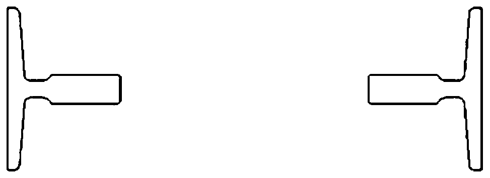
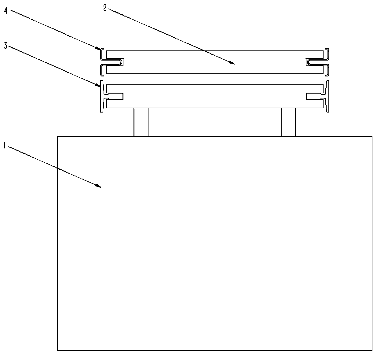
[0044] Such as Figure 4-13 As shown, a hollow guide rail oriented to the running direction of an elevator includes a hollow guide rail 4 formed by integral bending / rolling. The elevator car 1 and counterweight 2 are installed on the integrated hollow guide rail 4, and the hollow guide rail 4 is pressed The guide plate 5 is installed on the guide rail bracket 13, and the guide rail bracket 13 is installed on the wall. After the hollow guide rail 4 is bent / rolled and welded, it is formed to be connected with the counterweight guide shoe 9 on the counterweight 2 and the car on the car 1 respectively. The position of the car guide shoe 10 corresponds to the counterweight running guide groove 6 and the car running guide surface 7, and the hollow guide rail 4 guides the car 1 and the counterweight 2 in the running direction at the same time, and the car 1 and the counterweight 2. Under the guidance of the hollow guide rail 4, they move in opposite directions. Specifically, the car ...

Embodiment 2

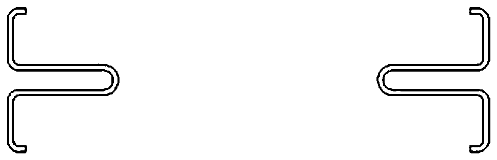
[0048] Such as Figure 5-14 As shown, a hollow guide rail oriented to the running direction of an elevator includes a hollow guide rail 4 formed by integral bending / rolling and welding. The car 1 and counterweight 2 of the elevator are installed on the hollow guide rail 4, and the hollow guide rail 4 passes through the guide rail The bracket 13 is installed on the wall, and the hollow guide rail 4 is bent / rolled to form a counterweight running guide that corresponds to and cooperates with the counterweight guide shoe 9 on the counterweight 2 and the car guide shoe 10 on the car 1 respectively. The slot 6 and the car running guide surface 7, the counterweight running guide slot 6 is U-shaped, and the hollow guide rail 4 guides the car 1 and the counterweight 2 in the running direction at the same time, and the car 1 passes the car guide shoe 10 in the The car moves up and down under the guiding action of the running guide surface 7, and the counterweight 2 moves up and down und...

Embodiment 3

[0055] Such as Figure 5-13 with Figure 15 As shown, a hollow guide rail oriented to the running direction of an elevator includes a hollow guide rail 4 formed by integral bending / rolling and welding. The car 1 and counterweight 2 of the elevator are installed on the hollow guide rail 4, and the hollow guide rail 4 passes through the guide rail The bracket 13 is installed on the wall, and the hollow guide rail 4 is bent / rolled to form a counterweight running guide that corresponds to and cooperates with the counterweight guide shoe 9 on the counterweight 2 and the car guide shoe 10 on the car 1 respectively. The slot 6 and the car running guide surface 7, the counterweight running guide slot 6 is U-shaped, and the hollow guide rail 4 guides the car 1 and the counterweight 2 in the running direction at the same time, and the car 1 passes the car guide shoe 10 in the The car moves up and down under the guiding action of the running guide surface 7, and the counterweight 2 move...


PUM


Abstract

The invention relates to a hollow guide rail for guiding the running direction of an elevator. The hollow guide rail comprises a hollow guide rail body formed by integrally bending/rolling, a lift carand a counterweight are installed on the hollow guide rail body, and a counterweight running guide groove and a lift car running guide face which correspond to and are matched with a counterweight guide shoe on the counterweight and a lift car guide shoe on the lift car respectively in position are formed on the hollow guide rail body. The lift car and the counterweight are guided at the same time through the hollow guide rail, the lift car moves up and down through the lift car guide shoe under the guide effect of the lift car running guide face, the counterweight moves up and down through the counterweight guide shoe under the guide effect of the counterweight running guide groove, and the movement direction of the lift car is opposite to the movement direction of the counterweight. According to the hollow guide rail for guiding the running direction of the elevator, the elevator area utilization rate is increased, the vertical mounting times of a lift car guide rail and a counterweight guide rail on site are reduced, the vibration problem of the lift car in the running period caused by inconsistent guiding perpendicularity is avoided, the complexity of mounting the lift car andthe counterweight guide rail on site is reduced, and the operation stability of the lift car is improved.

Description

technical field [0001] The invention belongs to the technical field of elevator accessories, and in particular relates to a hollow guide rail guiding the running direction of an elevator. Background technique [0002] Most of the structures of existing guide rails for elevators are as follows: Figure 1-3 As shown, the solid guide rail 3 is usually used to guide the running direction of the car 1, and the hollow guide rail 4 is usually used to guide the running direction of the counterweight 2. During use, the solid guide rail 3 and the hollow guide rail 4 are usually installed and fixed on the car 1 and counterweight 2, there are the following disadvantages: the installation occupies a large area, resulting in low space utilization of the car 1; the overall weight of the solid guide rail 3 is large, which requires high force on the elevator installation ground, and the installation and transportation process Because it is too heavy, the installation workers and transport wo...

Claims


Application Information

Patent Timeline
Patent Type & Authority Applications(China)
IPC IPC(8): B66B7/02B66B7/04
CPCB66B7/023B66B7/047
Inventor 袁忠才贾国涛吴斯琦
Owner 维亚帝电梯(苏州)有限公司
Why Eureka
Try Eureka