Screw pump driving device

A technology of driving device and screw pump, which is applied in the direction of wellbore/well valve device, drill pipe, mining fluid, etc. It can solve the problems of hurting people, low pressure, square clips loosening and flying out, etc., so as to improve the service life and prevent The effect of pipeline backflow, avoiding economic loss and environmental pollution

Pending Publication Date: 2020-05-22
LIAONING XINHUA INSTR CO LTD
View PDF0 Cites 0 Cited by
  • Summary
  • Abstract
  • Description
  • Claims
  • Application Information

AI Technical Summary

Problems solved by technology

[0002] At present, the surface driving devices generally used in oilfield screw pump wells are belt pulley general drive devices or screw pump direct drive devices. Most belt pulley general drive devices use ratchet and pawl anti-reverse methods without active torque release function. Once the mechanical structure fails , it is easy to cause problems such as the polished rod being thrown and bent, the outer shield being crushed, and the pulley breaking and flying out to hurt people, etc., which poses a relatively large safety hazard; , which is not conducive to the use of high-pressure working conditions in oil wells. At the same time, if the single mechanical seal leaks, maintenance operations must be carried out, resulting in a short operating cycle and economic losses due to maintenance operations; At this time, the electromagnetic brake cannot work normally, and there is still a potential safety hazard; because the square clip is exposed outside and placed at the top of the device, once the connection is loose, the rotation of the screw pump may cause the square clip to loosen and fly out, resulting in injury Or throwing the rod, there is a great potential safety hazard; when the existing screw pump direct drive device is installed, the clamping rod of the well sealing device is used alone for installation and disassembly operations. Accidental rotation can cause safety hazards
[0003] At the same time, the existing direct drive also has the following potential safety hazards: (1) When the equipment is installed, the BOP needs to clamp the polished rod, and then install the square clamp. Once the BOP clamp rod becomes loose or fails during the installation process, How can it cause the polished rod to rotate and cause danger?
(2) When a broken rod accident occurs, the liquid in the oil pipeline will flow back and be sprayed to the ground through direct drive, which will inevitably cause economic losses and environmental pollution
(3) When the motor needs to be repaired and disassembled, after the blowout preventer is sealed, a certain amount of pressurized liquid will be sealed between the blowout preventer and the square clip. At this time, there is a certain danger if the square clip is removed

Method used


Image

  • Screw pump driving device
  • Screw pump driving device
  • Screw pump driving device

Examples


Embodiment Construction

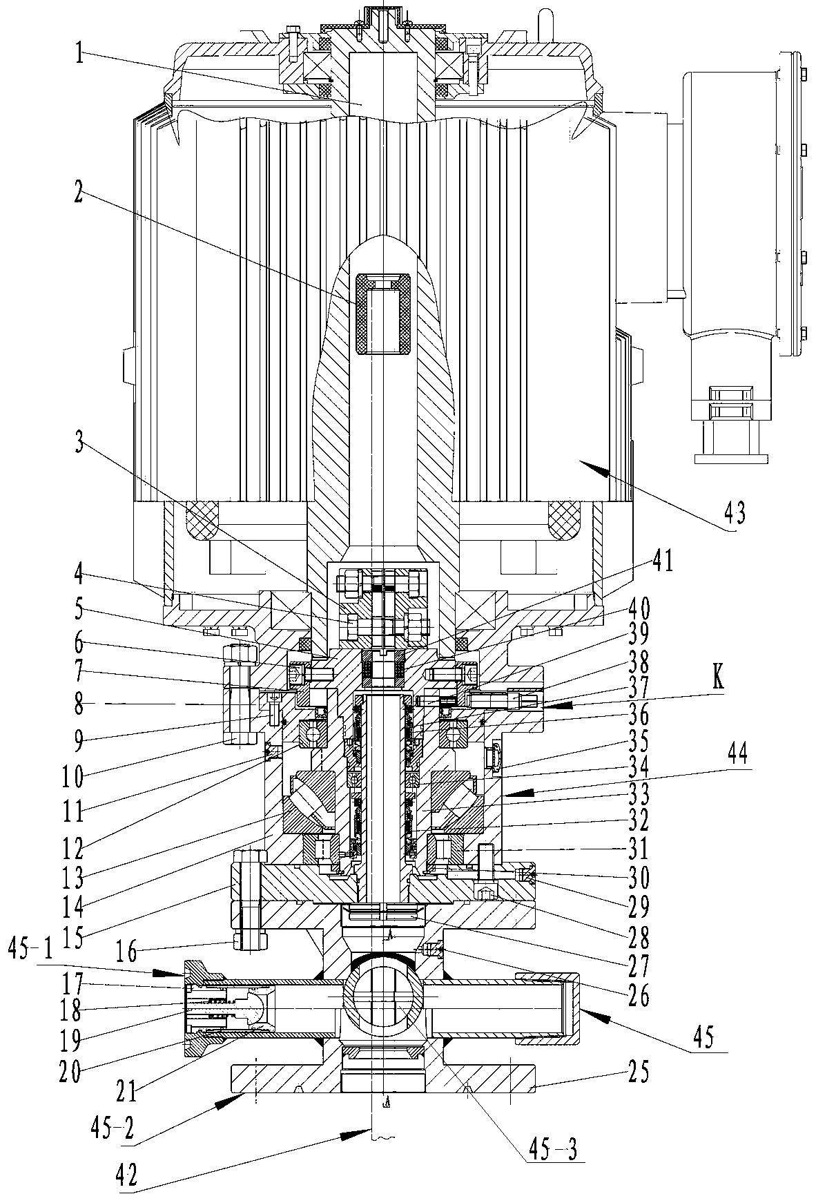
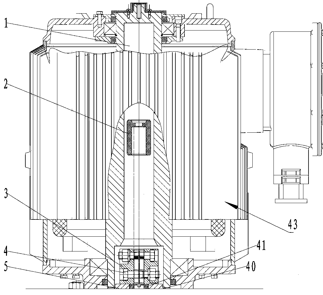
[0037] See figure 1 - Fig. 13, the specific structure of the present embodiment is, screw pump driving device, comprises drive motor 43, drive base 44, blowout preventer 45, sucker rod polished rod 42; Drive motor 43 sits on the upper end of drive base 44 and Fix by bolt nut II10,

[0038] The drive motor 43 includes a hollow motor shaft 1, a rubber tube sheath 2, and a square clip 3. The square clip 3 is symmetrical in two halves. The lower end of the square clip 3 has a T-shaped connection groove 3-1. The nut I4 clamps and fixes the polished rod 42 of the sucker rod; the rubber sleeve sheath 2 is set on the upper end of the polished rod 42 of the sucker rod;

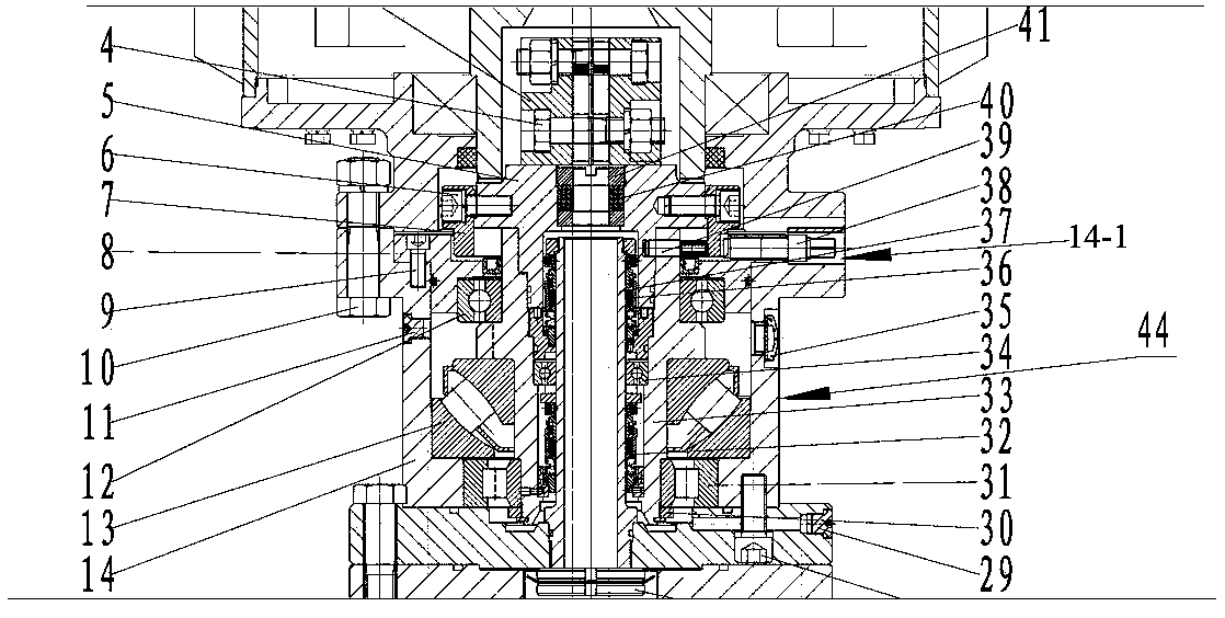
[0039]The drive base 44 includes a central tube 37, a main shaft 33, a central tube bearing 34, a cap head 5, a packing seal 40, a packing pressure cap 41, a brake flange 7, a brake top screw 38, and an upper mechanical seal 36 , lower mechanical seal 32, bearing cover 8, cylindrical pin 39, upper righting bearing 12...


PUM


Abstract

The invention relates to a screw pump driving device. The screw pump driving device comprises a driving motor, a driving base, a blowout preventer and a sucker rod polished rod; the driving motor comprises a hollow motor shaft, a rubber cylinder jacket and a square clamp; the driving base comprises a central tube, a main shaft, a central tube bearing, a cap head, a packing seal, a packing pressingcap, a braking flange, a braking jackscrew, upper and lower mechanical seals, a bearing cap, a cylindrical pin, an oil pointer, a carrying bearing, a base shell, an oil injection plug, a bottom flange, an oil drain plug and upper and lower alignment bearings; and the blowout preventer comprises a blowout preventer shell, a pressure relief screwed plug, a wellhead connector, a wellhead flange connector and a polished rod clamping device. By means of the driving device, the risk of flyout of the rod or the square clamp or other parts is avoided, risks caused by the failure of the blowout preventer are reduced, the service life of the motor is prolonged, pipeline backflow caused by falloff of the polished rod is prevented, the economic loss and environmental pollution caused by oil leakage are avoided, rigid friction between the polished rod and an inner hole of the hollow motor shaft is prevented, and the motor main shaft is protected.

Description

technical field [0001] The invention relates to a downhole operation device, in particular to a driving device for a screw pump. Background technique [0002] At present, the surface driving devices generally used in oilfield screw pump wells are belt pulley general drive devices or screw pump direct drive devices. Most belt pulley general drive devices use ratchet and pawl anti-reverse methods without active torque release function. Once the mechanical structure fails , it is easy to cause problems such as the polished rod being thrown and bent, the outer shield being crushed, and the pulley breaking and flying out to hurt people, etc., which poses a relatively large safety hazard; , which is not conducive to the use of high-pressure working conditions in oil wells. At the same time, if the single mechanical seal leaks, maintenance operations must be carried out, resulting in a short operating cycle and economic losses due to maintenance operations; At this time, the elect...

Claims


Application Information

Patent Timeline
Patent Type & Authority Applications(China)
IPC IPC(8): E21B43/00E21B33/06E21B34/02E21B19/10E21B17/10
CPCE21B17/1085E21B19/10E21B33/06E21B34/02E21B43/126
Inventor 梁伟成梁闯
Owner LIAONING XINHUA INSTR CO LTD
Why Eureka
Try Eureka