
an automatic cutting machine

A cutting machine and automatic technology, applied in the field of mechanical processing, can solve the problems of weak safety protection, small cutting range, noise pollution, etc., and achieve the effect of reducing the waiting time for feeding, improving efficiency and high positioning accuracy

Active Publication Date: 2020-07-17
德屹智能科技(扬州)有限公司
View PDF5 Cites 0 Cited by
  • Summary
  • Abstract
  • Description
  • Claims
  • Application Information

AI Technical Summary

Problems solved by technology

[0003] 1. Limited by the cutting direction (up and down), only one workpiece can be cut at a time, and the cutting range is small
[0004] 2. The safety protection is weak, and the tangential direction of the screen is facing the operation surface. Once it flies out, the workers will be greatly injured
[0005] 3. The noise pollution is serious, people working in this environment will affect their hearing

Method used


Image

  • an automatic cutting machine
  • an automatic cutting machine
  • an automatic cutting machine

Examples


Embodiment Construction

[0048] The present invention will be described in detail below in conjunction with specific embodiments. The following examples will help those skilled in the art to further understand the present invention, but do not limit the present invention in any form. It should be noted that those skilled in the art can make several changes and improvements without departing from the concept of the present invention. These all belong to the protection scope of the present invention.

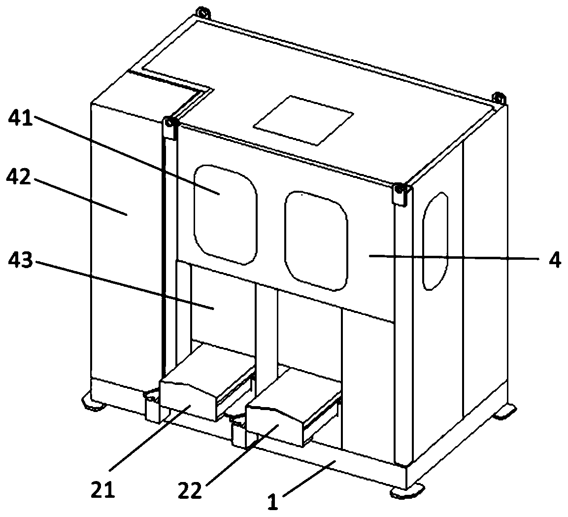
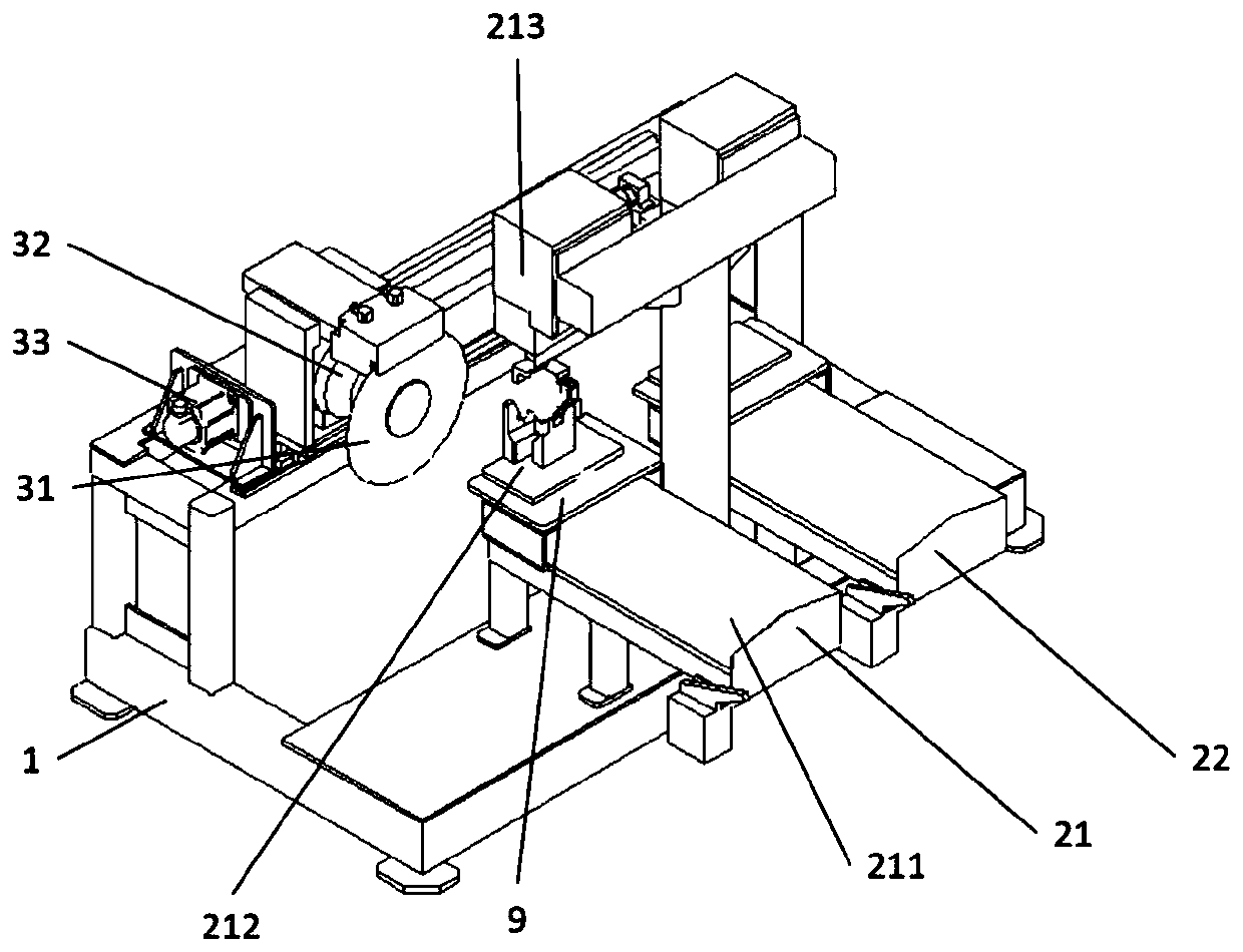
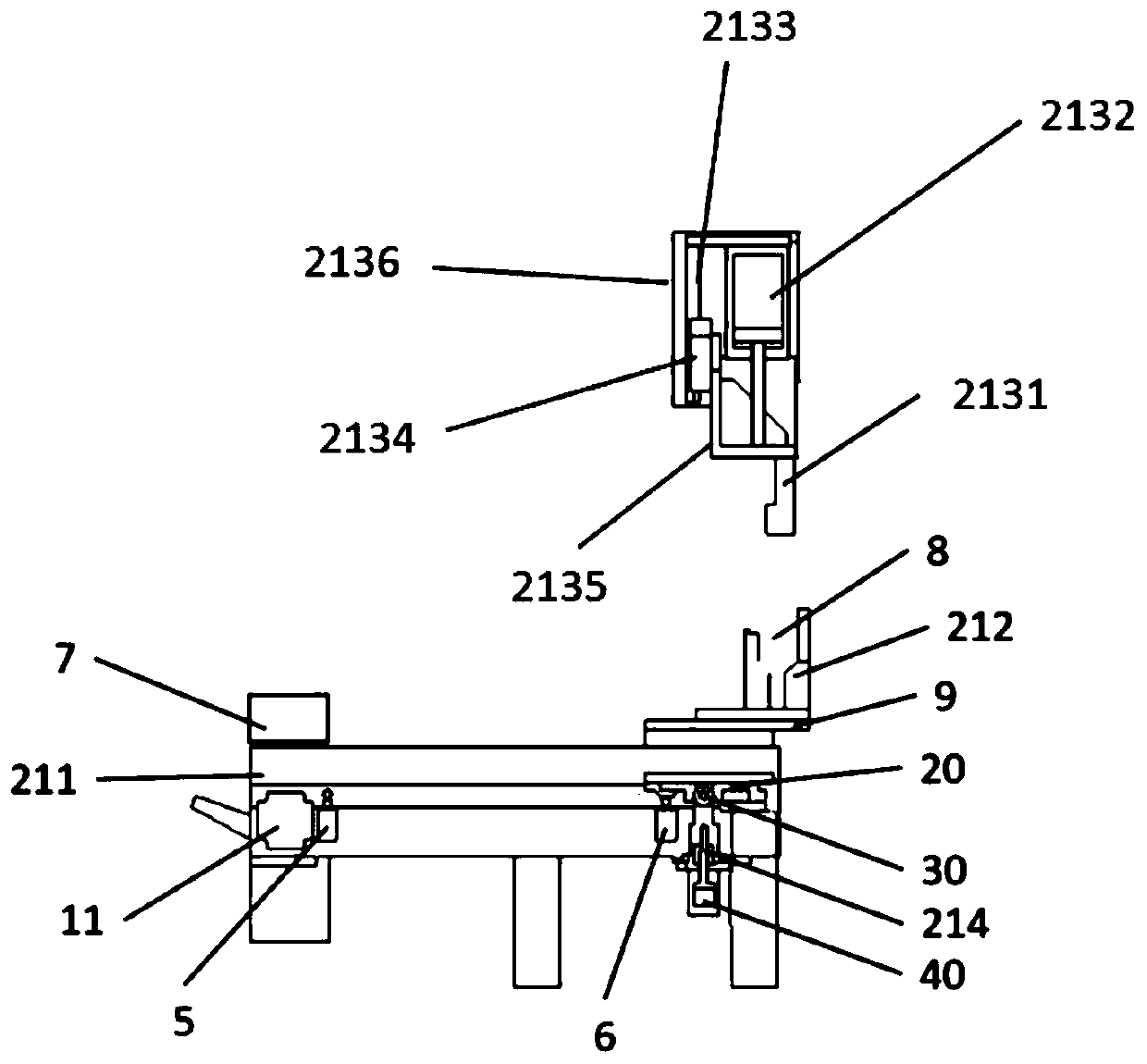
[0049] see Figure 1 to Figure 5 , an automatic cutting machine, including a main box 4, a base 1, several workpiece transmission devices, a workpiece cutting device 3, a first limit switch 5, a second limit switch 6. The base 1 is located at the bottom of the main box 4 and is connected with the main box 4 . The workpiece cutting device 3 is located inside the main box body 4 , and part of the workpiece transmission device extends out of the main box body 4 . In this embodiment, the automatic cutting...


PUM


Abstract

The invention discloses an automatic cutting machine. The automatic cutting machine comprises a base, a plurality of workpiece conveying devices and a workpiece cutting device, wherein the workpiece conveying device and the workpiece cutting device are arranged on the base; the workpiece conveying devices are arranged in parallel; and the arrangement direction of the workpiece cutting device is perpendicular to the arrangement direction of the workpiece conveying devices. Each workpiece conveying device comprises a feeding table, a workpiece positioning clamp, a transmission driving mechanismand a workpiece fixing mechanism, wherein the feeding table is fixed on the base; a movable table surface is arranged on the feeding table; the workpiece positioning clamp is arranged on the movable table surface; the transmission driving mechanism is connected with the movable table surface; and the workpiece fixing mechanism is positioned above the feeding table, The workpiece cutting device comprises a cutting disc and a cutting disc driving mechanism; the cutting disc is connected with the cutting disc driving mechanism; and the cutting disc driving mechanism is arranged on the base.

Description

technical field [0001] The invention relates to the technical field of mechanical processing, in particular to a device for automatically cutting workpieces. Background technique [0002] With the development of modern machining industry, machining is becoming more and more common. The use of workpiece cutting equipment is becoming more and more common. The currently used workpiece cutting equipment has the following problems: [0003] 1. Limited by the cutting direction (up and down), only one workpiece can be cut at a time, and the cutting range is small. [0004] 2. The safety protection is weak, and the tangential direction of the screen is facing the operation surface. Once it flies out, the workers will be greatly injured. [0005] 3. The noise pollution is serious, people working in this environment will affect their hearing. Contents of the invention [0006] In view of the defects in the prior art, the object of the present invention is to provide an automatic ...

Claims


Application Information

Patent Timeline
Patent Type & Authority Patents(China)
IPC IPC(8): B23D79/00B23Q7/00
CPCB23D79/00B23Q7/00
Inventor 钟波易昌
Owner 德屹智能科技(扬州)有限公司
Learn More